

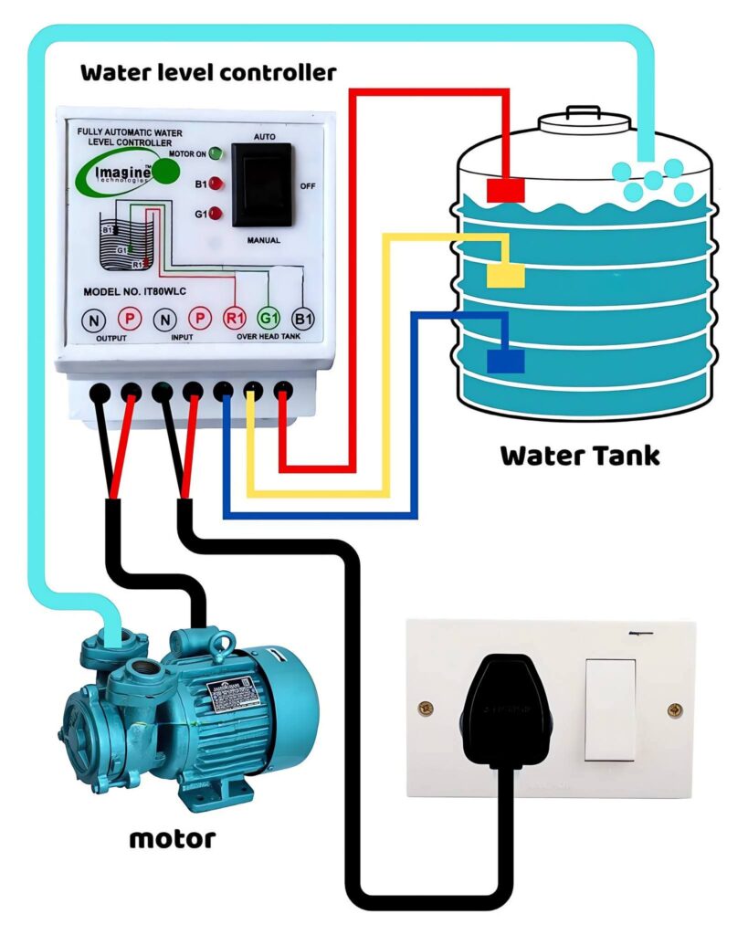
This wiring diagram demonstrates how to automate water tank filling using a water level controller and motor pump. The setup ensures the tank fills automatically when water levels drop and stops when it’s full — saving electricity and preventing overflow.
Key Components:
- Water Level Controller: Detects the water level and controls the pump automatically.
- Water Tank Sensors (B1, G1, R1): Measure low, medium, and full water levels.
- Motor Pump: Starts and stops based on the controller’s signal.
- Power Switch: Provides manual control for safety and maintenance.
Working Principle:
When the water level in the tank goes below the set limit, the controller activates the pump. Once the tank is full, the sensor signals the controller to turn the motor off. This system provides hands-free operation, energy efficiency, and consistent water supply.
⚙️ Tip: Use proper insulation and grounding to prevent electrical faults near water sources
Study smarter with VoltageLab
Built for electricians, apprentices, and electrical engineers who want faster practice and better exam prep.
⭐️ Join thousands of electricians upgrading their skills
