

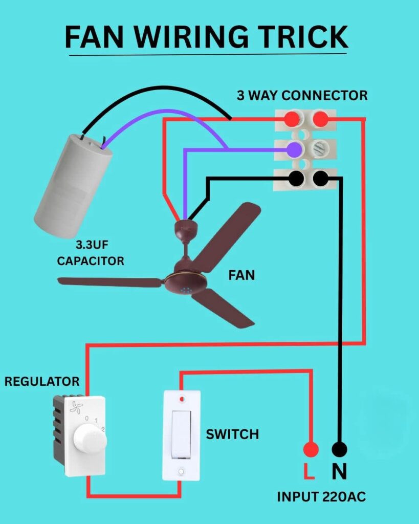
This diagram shows the complete fan wiring connection using a switch, regulator, and 3.3µF capacitor. It demonstrates how to properly wire a ceiling fan for safe operation and adjustable speed control.
Key Components:
- Switch: Controls power to the fan.
- Regulator: Adjusts the fan speed.
- Capacitor (3.3µF): Helps start the fan and maintain rotation.
- 3-Way Connector: Used for clean and secure wire joining.
Working Principle:
When the switch is turned ON, power flows through the regulator to the fan motor, while the capacitor provides the phase shift needed for the fan to start rotating. The neutral (N) and live (L) wires supply the 220V AC input.
⚡ Tip: Always ensure the capacitor value matches your fan’s rating for smooth operation and efficiency.
⚡ AI-Powered Electrician App
Study smarter with VoltageLab
Built for electricians, apprentices, and electrical engineers who want faster practice and better exam prep.
⭐️ Join thousands of electricians upgrading their skills
