

What is the EGC?
The Equipment Grounding Conductor (EGC) is the primary safety mechanism of the electrical system.
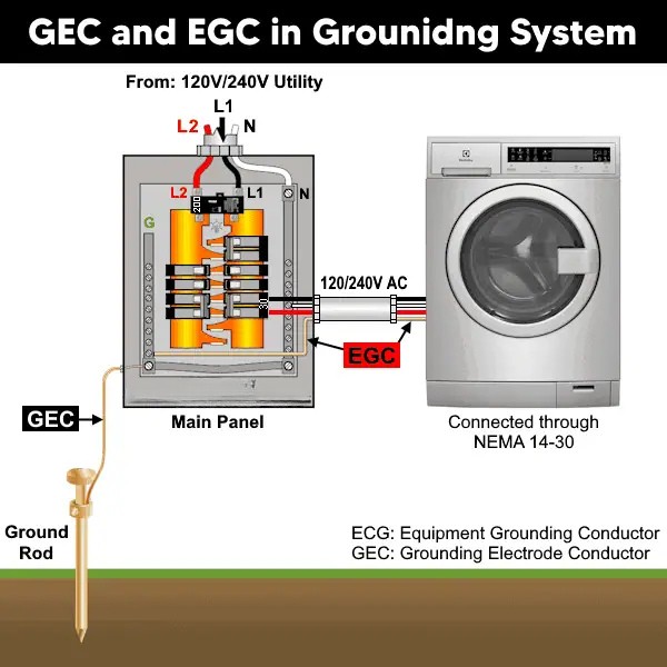
While the Grounding Electrode Conductor (GEC) connects the system to the earth, the EGC connects all non-current-carrying metal parts (motor frames, outlet boxes, conduit) back to the main service panel.
Study smarter with VoltageLab
Built for electricians, apprentices, and electrical engineers who want faster practice and better exam prep.
⭐️ Join thousands of electricians upgrading their skills
The Two Main Jobs of the EGC:
- Safety: It ensures that metal parts do not stay energized if a hot wire comes loose.
- Tripping the Breaker: It creates a low-resistance path for fault current to flow back to the source, forcing the Overcurrent Protective Device (OCPD) (breaker or fuse) to trip immediately.
Permitted Types (NEC 250.118)
In the USA, the EGC isn’t always a wire. The NEC permits specific raceways to serve as the ground:
- Wire: Copper or Aluminum (Bare, Green, or Green/Yellow striped).
- Conduit: Rigid Metal Conduit (RMC), Intermediate Metal Conduit (IMC), and Electrical Metallic Tubing (EMT).
- Note: Flexible Metal Conduit (FMC) has strict length limits to be used as a ground.
⚠️ Critical Warning: The Main Bonding Jumper
- One Connection Only: The Neutral and the EGC are bonded together at only one point: the Main Service Disconnect.
- The Component: This connection is made using the Main Bonding Jumper (MBJ). If this is missing, the breaker will NOT trip during a ground fault.
- Never Downstream: Never connect Neutral and Ground together in sub-panels or outlets. This creates dangerous “ground loops.”
How to Size the EGC
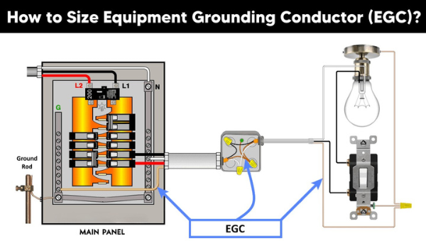
Unlike the GEC (which is sized by wire size), the EGC is sized based on the rating of the Overcurrent Device (Breaker/Fuse) protecting the circuit.
NEC Table 250.122 Reference
| Breaker / Fuse Rating (Amps) | Copper EGC | Aluminum / Cu-Clad |
| 15 A | 14 AWG | 12 AWG |
| 20 A | 12 AWG | 10 AWG |
| 30 A | 10 AWG | 8 AWG |
| 40 A | 10 AWG | 8 AWG |
| 60 A | 10 AWG | 8 AWG |
| 100 A | 8 AWG | 6 AWG |
| 200 A | 6 AWG | 4 AWG |
| 300 A | 4 AWG | 2 AWG |
| 400 A | 3 AWG | 1 AWG |
| 500 A | 2 AWG | 1/0 |
| 600 A | 1 AWG | 2/0 |
| 800 A | 1/0 | 3/0 |
| 1000 A | 2/0 | 4/0 |
| 1200 A | 3/0 | 250 kcmil |
| 1600 A | 4/0 | 350 kcmil |
| 2000 A | 250 kcmil | 400 kcmil |
| 2500 A | 350 kcmil | 600 kcmil |
| 3000 A | 400 kcmil | 750 kcmil |
| 4000 A | 500 kcmil | 1000 kcmil |
| 5000 A | 700 kcmil | 1250 kcmil |
3 Special Rules You Must Know
1. Voltage Drop Upsizing (NEC 250.122(B))
If you increase the size of your hot wires to account for voltage drop (long distance), you must increase the size of your EGC proportionately.
Example: If you double the circular mils of your hot wire, you must double the circular mils of your ground wire.
2. Parallel Conductors (NEC 250.122(F))
When running parallel conduits for large feeders:
- The EGC must be installed in every raceway.
- The EGC in each raceway must be full size based on the breaker rating. Do not divide the ground size by the number of conduits.
3. High-Fault Currents
In industrial settings where available fault currents exceed 10,000 Amperes, standard EGC sizing may not be sufficient. You may need to upsize the EGC to ensure it doesn’t melt before the breaker clears the fault.
⚠️ Critical Installation Rules (Must Read)
1. Voltage Drop Upsizing (NEC 250.122(B)) If you upsize the ungrounded (hot) conductors to reduce voltage drop, you must upsize the EGC proportionately.
Rule: The percentage increase in the EGC size must match the percentage increase of the hot wires.
2. Physical Protection (NEC 250.120(C))
- Smaller than 6 AWG: Must be protected by a raceway or cable armor to prevent physical damage.
- 6 AWG and larger: Can be run exposed if securely fastened to the surface.
3. Aluminum Restrictions (NEC 250.120(A)) Aluminum EGCs cannot be installed in direct contact with earth (dirt) or concrete (masonry), as they will corrode.
4. Flexible Metal Conduit (Flex) A separate wire-type EGC is required inside the flex if:
- The circuit is over 20 Amps.
- The flex length is greater than 6 feet (1.8m).
5. Parallel Conductors When running parallel conduits:
- An EGC must be installed in each raceway.
- It must be full size based on the breaker rating (do not divide the size).
6. Routing & Continuity
- Routing: The EGC must be run within the same raceway or cable as the circuit conductors.
- Splicing: Splices must be irreversible (crimp or exothermic weld).
- Termination: Must be securely connected to the panel enclosure, bonding jumpers, and devices using approved terminals (NEC 250.8).
Examples of EGC Sizing and Calculations
Example 1: What is the suitable size of EGC for a 15 and 20 -Amp circuit breakers?
Solution:The rating of overcurrent devices used for the most common household applications are 15-amp and 20-amp.
Refereeing to the NEC table 250.122;
Study smarter with VoltageLab
Built for electricians, apprentices, and electrical engineers who want faster practice and better exam prep.
⭐️ Join thousands of electricians upgrading their skills
For 15-Amp Circuit
- Copper EGC: 14 AWG
- Aluminum / Copper-Clad Aluminum EGC: 12 AWG
For 20-Amp Circuit
Aluminum / Copper-Clad Aluminum EGC: 10 AWG
Copper EGC: 12 AWG
Example 2: What is the required size of EGC for a 60-Amp circuit breaker?
Solution:
- OCPD Rating: 60 Amps
- Referencing NEC Table 250.122:
- Copper EGC: 10 AWG
- Aluminum or Copper-Clad Aluminum EGC: 8 AWG
