

🏠 Ground an Electrical Panel: NEC Requirements
Proper grounding is the non-negotiable foundation of electrical safety. It ensures stability and provides a critical path for fault current, preventing severe shocks and fire hazards. This guide covers the essential principles and procedures for grounding an electrical panel per the National Electrical Code (NEC) Article 250.
🔄 Grounding vs. Bonding: The Core Distinction
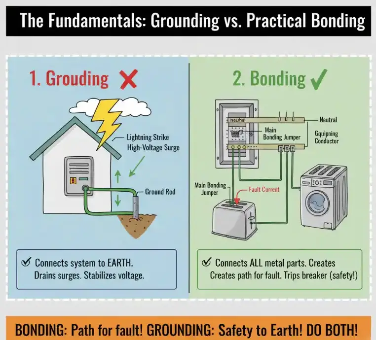
While often confused, grounding and bonding serve two separate safety functions:
| Concept | Purpose | NEC Connection |
| Grounding | Connecting the system to the earth (via a rod) to stabilize voltage and dissipate high-voltage events (e.g., lightning). | Grounding Electrode System |
| Bonding | Connecting all non-current-carrying metal parts (enclosures, conduits) together to create a low-impedance fault path back to the source. | Main Bonding Jumper (MBJ) |
In short, bonding creates the path for the fault current, and grounding ensures the safety device (breaker) operates to clear that fault.
🌎 The Grounding Electrode System

The grounding electrode is the physical component that connects your electrical system to the earth.
Electrode Requirements (NEC 250.53)
- Minimum Contact: A rod electrode must have a minimum of 8 feet of its length in direct contact with the soil.
- Resistance Rule: If the resistance to ground of a single rod measures more than 25 ohms, a second rod must be installed.
- Rod Types: Copper-Bonded Steel (common), Galvanized Steel, or Solid Copper (premium).
🛠️ Core NEC Conductors and Connections (Article 250)
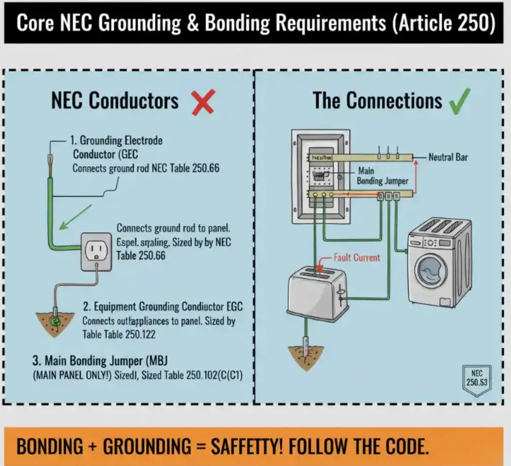
NEC Article 250 outlines the specific wires and jumpers needed for a safe system:
| Component | Function | Sizing Requirement |
| Grounding Electrode Conductor (GEC) | Connects the ground rod to the grounding bus bar in the main panel. | Sized according to NEC Table 250.66, based on service-entrance conductor size. |
| Equipment Grounding Conductor (EGC) | The safety wire running with branch circuits (bare copper/green wire) to provide the low-impedance fault path back to the panel. | Sized according to NEC Table 250.122, based on the circuit’s breaker rating. |
| Main Bonding Jumper (MBJ) | A screw, strap, or wire that physically connects the neutral bus bar and the grounding bus bar in the main panel only. | Sized according to NEC Table 250.102(C)(1). |
🛑 Main Panel vs. Subpanel: The Crucial Safety Rule
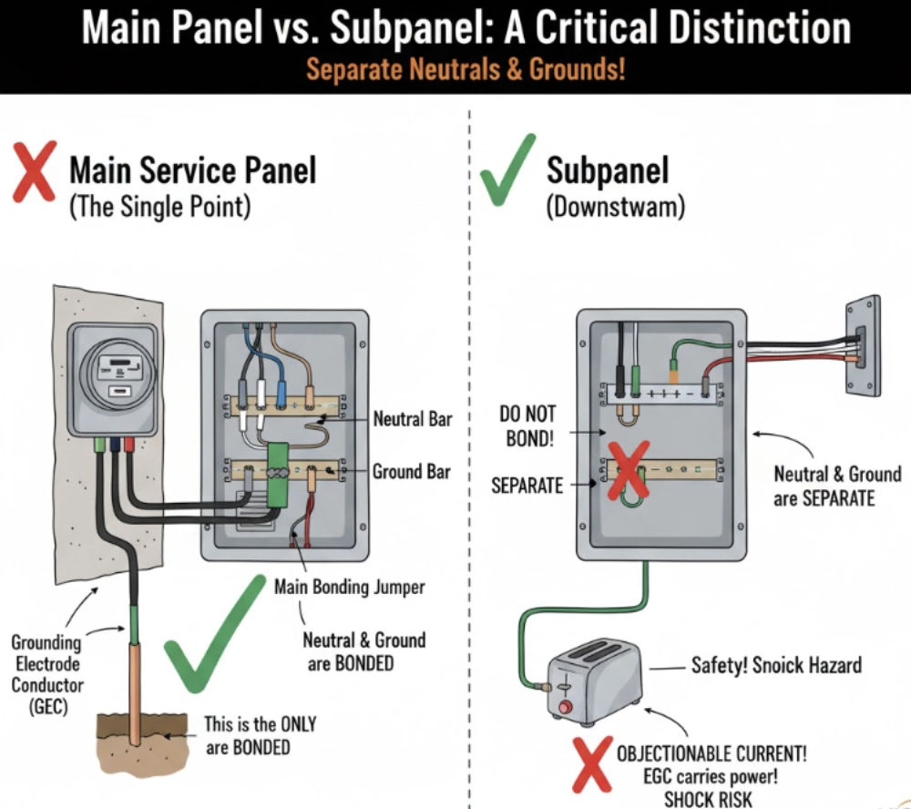
This distinction is the most critical rule in grounding and bonding:
1. Main Service Panel
- Bonding Required: The neutral bus bar and the ground bus bar must be connected by the Main Bonding Jumper (MBJ). This is the single point where the system is connected to the earth ground.
2. Subpanels (Panels Fed from the Main)
- Isolation Required: The neutral and ground bus bars must be kept separate (isolated). The MBJ is not installed in a subpanel.
- Why? Bonding the neutral and ground in a subpanel creates objectionable current, allowing normal return current to flow on the equipment grounding conductors and metal enclosures, resulting in a severe shock hazard.
✅ Step-by-Step Installation Summary
⚠️ Safety First: Always shut off and verify the panel is de-energized using a voltage tester before touching internal components. Hire a licensed electrician.
- Install the Rod: Drive the $\mathbf{8-foot}$ grounding rod into the earth near the panel (at least 6 feet from other electrodes).
- Connect the GEC: Run the correctly sized GEC (Table 250.66) from the rod (using a listed clamp) to the main grounding bus bar inside the panel.
- Confirm the MBJ: Ensure the Main Bonding Jumper (screw or strap) is securely connecting the neutral bus to the ground bus—only in the main panel.
- Wiring: Connect all EGCs (bare or green wires) to the grounding bus bar.
❌ Common Mistakes to Avoid
- Bonding Neutral and Ground in a Subpanel: The most dangerous violation (objectionable current).
- Undersized Conductors: Failing to use NEC Table 250.66 (GEC) or 250.122 (EGC).
- Insufficient Rod Depth: Less than 8 feet of contact with the soil.
- Loose Connections: All connections must be tight to ensure a reliable, low-resistance path.
