Definition:
A PN junction diode works in two modes depending on how the external voltage is applied:
- Forward Bias: Current flows easily.
- Reverse Bias: Current is almost blocked.
Forward Bias (GIF Reference):
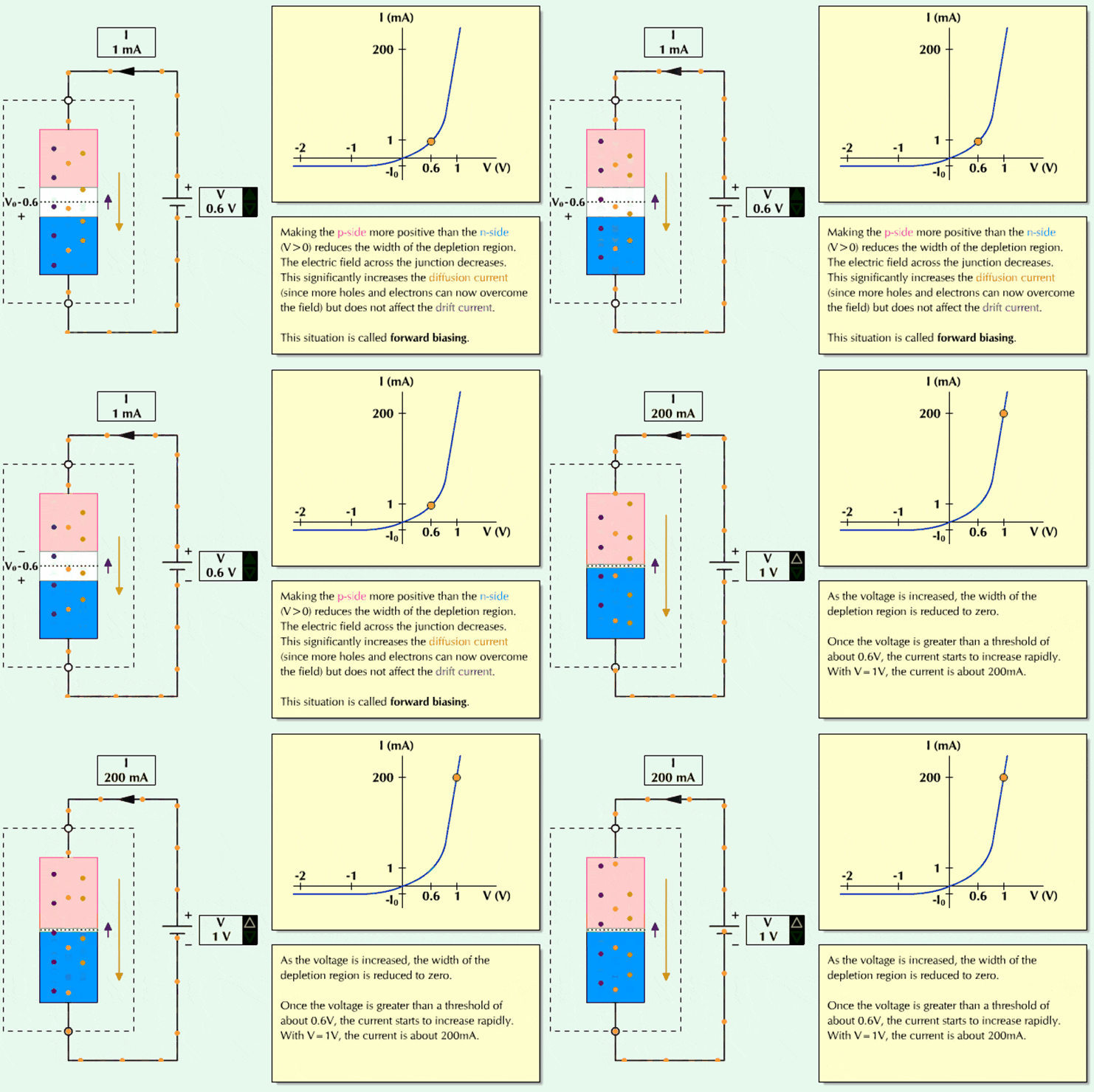
In the GIF:
- The P-side (pink) is connected to the positive terminal of the battery, and the N-side (blue) is connected to the negative terminal.
- This reduces the depletion region width, making it easier for electrons (from N-side) and holes (from P-side) to cross the junction.
- Once the applied voltage reaches around 0.6V (for silicon diode), a large current begins to flow, as shown in the I–V curve on the right.
- This is called forward biasing.
Reverse Bias (concept explanation):
- If the battery is reversed (P-side negative, N-side positive):
- The depletion region widens, blocking the movement of carriers.
- Only a tiny leakage current flows due to minority carriers.
- The diode effectively blocks current flow.
Quick Recap:
- Forward Bias: P-side positive, N-side negative → Current flows once voltage > threshold (~0.6V for silicon).
- Reverse Bias: P-side negative, N-side positive → Almost no current flows.
- Graph Insight: The I–V curve shows very small current in reverse, and a rapid increase in current once forward voltage passes the threshold.


