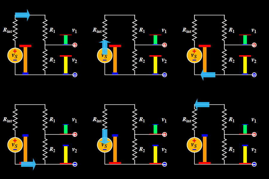
This diagram explains the Voltage Divider, a basic DC circuit used to split a single supply voltage into smaller, desired output voltages.
A voltage divider uses two resistors in series to divide the input voltage proportionally.
It is widely used in sensors, reference circuits, biasing, and signal level adjustments.
Key Components:
- Voltage Source (Vs): Provides the input DC voltage.
- Internal Resistance (Rint): Represents the internal resistance of the voltage source.
- Resistors (R1 and R2): Connected in series to divide the input voltage into two output voltages.
- Output Voltages (v₁ & v₂): The voltages measured across R1 and R2 respectively.
Working Principle:
When two resistors are connected in series, the total voltage divides according to their resistance values.
The voltage across each resistor is given by:
Voltage across R1 (V1):
V1 = Vs * (R1 / (R1 + R2))
Voltage across R2 (V2):
V2 = Vs * (R2 / (R1 + R2))
In the GIF:
- The source voltage is applied across the entire series network
- R1 receives the upper portion of the voltage (v₁)
- R2 receives the remaining portion (v₂)
The animation shows how the height of the colored bars represents the voltage at each point, making it easy to visualize how voltage decreases step by step down the divider.
⚡ Tip:
Voltage dividers work best with high resistor values and low-current loads.
Heavy loads can change the output voltage and reduce accuracy—use buffers when needed.


