


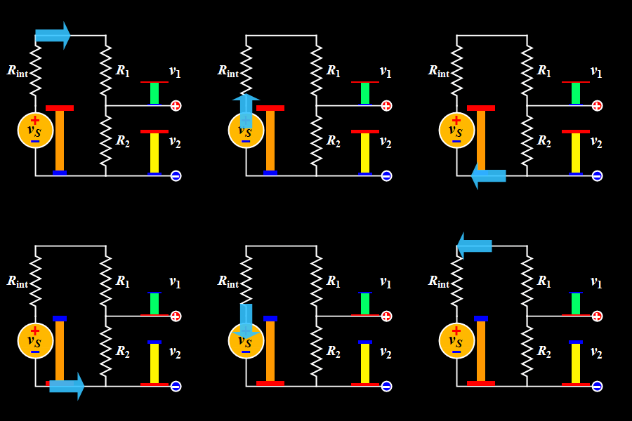
This diagram explains the Voltage Divider, a basic DC circuit used to split a single supply voltage into smaller, desired output voltages.
A voltage divider uses two resistors in series to divide the input voltage proportionally.
Study smarter with VoltageLab
Built for electricians, apprentices, and electrical engineers who want faster practice and better exam prep.
⭐️ Join thousands of electricians upgrading their skills
It is widely used in sensors, reference circuits, biasing, and signal level adjustments.
Key Components:
- Voltage Source (Vs): Provides the input DC voltage.
- Internal Resistance (Rint): Represents the internal resistance of the voltage source.
- Resistors (R1 and R2): Connected in series to divide the input voltage into two output voltages.
- Output Voltages (v₁ & v₂): The voltages measured across R1 and R2 respectively.
Working Principle:
When two resistors are connected in series, the total voltage divides according to their resistance values.
The voltage across each resistor is given by:
Voltage across R1 (V1):
V1 = Vs * (R1 / (R1 + R2))
Voltage across R2 (V2):
Pass your electrical exam the first time
Practice real NEC exam questions with full code-referenced explanations and progress tracking — built for journeyman, master and apprentice exam prep.
Thousands of NEC practice questions with code-referenced answers
V2 = Vs * (R2 / (R1 + R2))
In the GIF:
- The source voltage is applied across the entire series network
- R1 receives the upper portion of the voltage (v₁)
- R2 receives the remaining portion (v₂)
The animation shows how the height of the colored bars represents the voltage at each point, making it easy to visualize how voltage decreases step by step down the divider.
⚡ Tip:
Voltage dividers work best with high resistor values and low-current loads.
Heavy loads can change the output voltage and reduce accuracy—use buffers when needed.
FREE PRACTICE TOOL
Think you'd pass this on a real exam?
Test what you just read with instant-feedback quizzes built around real code questions — not generic trivia.
5
Code standards
10,000+
Active learners
100%
Free to start
Instant explanations on every answer, right or wrong
NEC, BS7671, AS/NZS, CEC, and DIN VDE covered
Bite-sized quizzes you can finish in 5 minutes
No signup required to try your first quiz
No account needed · Takes less than 2 minutes