

We all heard about relay but we are seeking out a simple relay wiring diagram. It’s a very popular topic for all electrical engineering students. Today I will discuss it in an easy manner. Let’s start. Before going into details, I want to introduce the relay first.
What is relay?
Imagine, it’s rainy season. It’s raining cats & dogs outside. The whole environment becomes dark. Your mother tells you to switch on the incandescent bulb. But, you feel very dizzy. You are taking a rest with a blanket. You are thinking that, if you were a magician, you can switch on the light by voice.
Study smarter with VoltageLab
Built for electricians, apprentices, and electrical engineers who want faster practice and better exam prep.
⭐️ Join thousands of electricians upgrading their skills
In this case, you Don’t need to be a magician. Relay is a magical switching device in this circumstance that acts automatically. Now, a question is arising in your mind that, how this magic is done?. Actually, it’s not rocket science. It’s a voice-activated home automation system.
Basic Construction of Relay:
In order to realize the function of the relay, you have to know its basic construction of it. Besides, it helps you to draw a relay wiring diagram. Relay mainly consists of two parts:
- Electromagnetic Part
- Switching Part
Types of Relay:
- SPST Relay (Single Pole Single Throw) which contains 4 pin
- SPDT Relay (Single Pole Double Throw) which contains 5 pin
- DPDT Relay (Double Pole Double Throw) which contains 8 pin
Among the above three types of relays, SPST and DPDT are less common. Generally, SPDT relays are available almost everywhere and with this relay, we do a lot of work. Note that, the relay works in both AC and DC sources.
Details Postmortem of Relay:
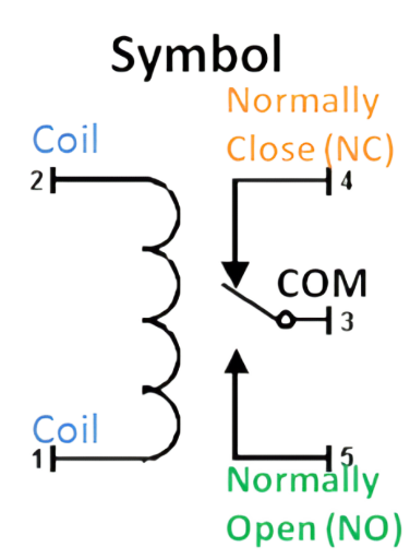
For understanding relay wiring drawing you have to be acquainted with all relay pins.SPDT (Single Pole Double Throw) relays are commonly used. So the detailed postmortem of this relay is highlighted. It is said above that the pin number of such relays is five. The identification of the relay pin is given below:
Pin no 1:
Usually, pin number 1 is a coil (+/-). Normally, the voltage at which the relay coil is turned on is the operating volt of the relay. The amount of value given in the coil is taken into account and the connection is given with the help of the resistor and the capacitor. Normally, no positive or negative of the relay is specified. Any of the two ends of this coil can be connected to the supply.
Pin no 2:
Pin no 2 also holds the coil. It acts according to the same manner of pin no 1.
FREE PRACTICE TOOL
Think you'd pass this on a real exam?
Test what you just read with instant-feedback quizzes built around real code questions — not generic trivia.
5
Code standards
10,000+
Active learners
100%
Free to start
Instant explanations on every answer, right or wrong
NEC, BS7671, AS/NZS, CEC, and DIN VDE covered
Bite-sized quizzes you can finish in 5 minutes
No signup required to try your first quiz
No account needed · Takes less than 2 minutes
Pin no 3:
Pin number 3 is a common pin. Now, you may ask that, what’s the common pin again? This is a pin to which normally open and normally close pins are connected. This means that it is used to connect anyone between normally open and normally closed pins. In a word, this pin is called a common pin.
Pin no 4:
Pin number 4 is NC (normally close). In normal conditions, the normally closed pin is in the closed state. If the power is not connected to the relay coil, the normally closed pin is in a short state connection with its common pin.
Pin no 5:
Pin number 5 is NO (normally open). Normally open pin is in open state under normal conditions. If the relay coil is not connected to electricity, the normally open pin is open with its common pin in the open state. This pin is connected to the common pin when the electricity is supplied. Switching is usually done through the connection of the common pin and the normally open pin. A picture is given in below for better understanding.
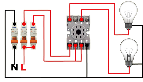
8 pin relay:
- There are also 2 coil pins where its AC/DC rated voltage will be applied. Note that, the relay coil does not have polarity. Any one of the two ends of the coil pin can be worked as positive/negative.
- Two common pins
- 2 normally open pins
- 2 normally close pins
11 pin relay:
- 2 coil pins where its rated voltage will be applied
- Three common pins
- 3 Normally Open Pins
- 3 normally close pins
14 pin relay:
- 2 coil pins for voltage supply
- Four common pins
- 4 normally open pins
- 4 normally close pins
Basic Operation of Relay:
Now, I want to represent the basic operation of relay simply. For better understanding, I describe it as list:
- Human life is impossible without brain. Similarly, the brain of this relay is an electromagnet.
- When we connect the operating voltage supply, the electromagnet will be energized.
- Then a powerful magnetomotive force will create in the control circuit.
- This Magnetomotive force helps the spring to move the armature body of NO and NC contact.
- When there is no power supply, then it is abiding in NO position.
- But while supplying the DC/AC power, the relay activates and remains in NC position. Then the load circuit gets power and the load (Fan, Light) turns on.
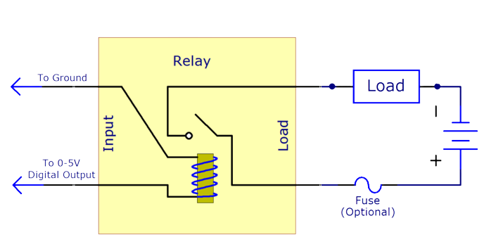
Now, you may ask how you will connect a relay to a power supply with a load. For this purpose, I am providing a very simple wiring diagram of the relay. Let’s see.
Relay Wiring Diagram With Load:
In the above picture relay wiring diagram is presented in a very simple manner. So, this article will be helpful for electrical engineering students indeed.
Read More Articles
Introduction To Ice Cube Relay And Its Wiring Diagram
Discussion about Load Break Switch
FREE PRACTICE TOOL
Think you'd pass this on a real exam?
Test what you just read with instant-feedback quizzes built around real code questions — not generic trivia.
5
Code standards
10,000+
Active learners
100%
Free to start
Instant explanations on every answer, right or wrong
NEC, BS7671, AS/NZS, CEC, and DIN VDE covered
Bite-sized quizzes you can finish in 5 minutes
No signup required to try your first quiz
No account needed · Takes less than 2 minutes
