

A single line diagram is very important in a power system. We can easily visualize or describe the three-phase power system in a single-line diagram. Today we will discuss the substation three-phase single-line diagram explanation.
Instead of three wires for a three-phase line, one wire is used for describing the circuit breaker, transformer, capacitor, and busbar by the standard symbol. Single-line diagram is also called a blueprint of Electrical system analysis.
Study smarter with VoltageLab
Built for electricians, apprentices, and electrical engineers who want faster practice and better exam prep.
⭐️ Join thousands of electricians upgrading their skills
With the help of a single-line diagram, we can easily design a substation. We have shown some of the symbols of the single-line diagram.
Symbol
Also, many other symbols can be used in single-line diagrams. CT, PT, VCB, and ACB symbols can be a bit different. But it won’t be completely different. Here is a single-line diagram:
Single-line diagram
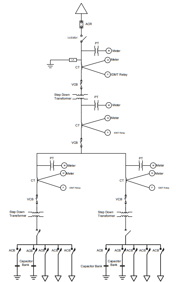
The above single-line diagram is drawn by auto-cad software. With the help of this single-line diagram, we can easily understand what we should keep in mind for designing a substation.
Before designing a substation we have to do a calculation. It includes cable selection of LT and HT side, circuit breaker selection, PT and CT selection, busbar selection, power factor improvement calculation, etc. We will discuss these in other articles.
That was all for today.
If you have any queries on substation three-phase single-line diagram explanation, you can ask in the comment box.
You can also read: What are the Components of a Substation
Practice more with electrical quizzes
NEC · BS7671 · AS/NZS · CEC · DIN VDE
