

Suppose, you are talking with your friend over the mobile phone. You both can’t talk at the same time spontaneously. When your friend will talk, you have to be on pause. On the contrary, when you will talk, your friend ought to be on pause. Would you implement this manner in the switching system? Yes, we can easily apply this manner in the case of the transfer switch. Now, it’s very natural to arise a question in your mind that, what is a transfer switch? How does it act? Let’s discuss transfer switch installation and operation.
What is transfer switch?
Each industry has a backup generator besides having the supply line of the power distribution company. Because, when the power supply becomes a failure, the backup generator begins to run. Here we can develop a mutual switching system. When the utility line is off, the generator line will be on. On the contrary, when the utility line is on, the generator line will be off. In this function, we can use a switching system named transfer switch. It is also known as a change-over switch.
Study smarter with VoltageLab
Built for electricians, apprentices, and electrical engineers who want faster practice and better exam prep.
⭐️ Join thousands of electricians upgrading their skills
Transfer Switch Installation Process
Transfer switch installation systems can be manual or automatic. Now I am going to tell the procedure in a short and simple manner.
At first, you have to turn off the main circuit breaker of the electrical panel. Then make a list of very essential loads of your home which is crying need after power failure. Now, we have to choose a suitable size for the generator transfer switch.
How to choose a suitable size for the transfer switch installation?
For choosing a suitable size for the transfer switch you have to obey the following two factors. They are:
- The volts and amperage rating and capacity specifically.
- Generator burden or loads which will be connected to generator.
The perfect size of the generator will fetch a good response in this switching system. If the size of the generator is not that large then it will be much easier to install a budget-friendly transfer switch than a large transfer switch.
How Electrical Panel can be a factor here?
If a manual transfer switch will be installed then the size of the transfer switch must be rated as the same size as the electrical panel. So, if the generator power will be providing power for a 220 volt 125 amp panel then the transfer switch must be rated for at least 220 volts 125 amps.
One mentioning fact is that we have to establish the transfer switch 1.5 feet away from the main electrical panel.
You can set up this switching system automatically also. But how? Let’s know this procedure too. We will discuss this with a controlling diagram.
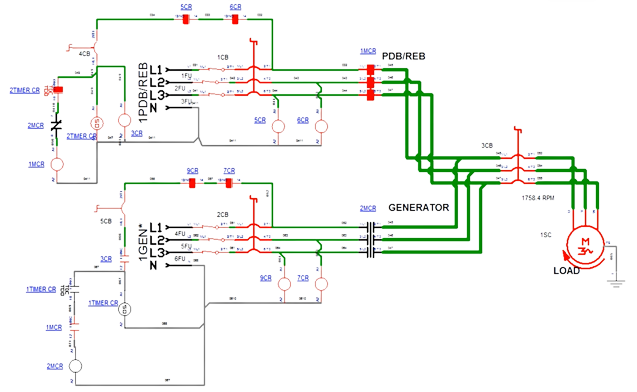
- The circuit diagram suggests that to make this circuit, two magnetic conductors are required.
- We know that wherever there is automation, there is a magnetic conductor.
- One is for the magnetic contact generator line and the other for the power distribution company line.
- Another important device in this system is the timer.
What is the purpose of using this timer?
Now the question may be, why do you need a timer here?
- Suppose, the line of your generator is running.
- Now the electricity of supply line has come up.
- By doing this, there is a possibility of flushing or short circuit between the two lines.
- So if you set 5-7 seconds in the timer, the line of power distribution company will not start immediately.
- It will start within a few seconds. Then there will be no possibility of an unexpected accident.
Now, again take a look at the figure. Here, Two magnetic contactors are marked with 1MCR, 2MCR.
- 1MCR for power distribution company line and 2MCR generator for the line. These are three-phase magnetic conductors.
- Three supply lines L1, L2, L3 entered the magnetic contactor.
- If you look at the far left side of the circuit diagram, you will see that there is a normally open contact of 2MCR at 1MCR, the normally open contact of 1MCR at 2MCR is interlocked.
- By doing this, when the normally open contact of 1MCR is closed (the power distribution company line is turned on), the 2MCR will be normally open.
- Again, when the normally open contact of the 2MCR closes (the generator line is turned on), the normally close contact of the 1MCR will open (the power distribution company line will be off).
Read More Articles
What is Ground Switch? Why it is Used?
PFI Panel Circuit Diagram | Power Factor Improvement Diagram
