

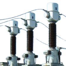
You are walking through a cool and calm street. Suddenly, you discovered a power substation laying beside the street. There are many kinds of equipment with a view to setting up a substation. Suddenly, you notice a bunch of CT (current transformer) in the substation. All of a sudden, a question hit upon your mind why we don’t use an ammeter in a high voltage substation? Let’s discuss the topic by drawing 3 Phase CT Meter Connection Wiring Diagram.
What is a Current Transformer?
The short-term CT stands for current transformers. A wrong conception goes of the maximum number of people that, the transformer is only used for stepping up or down the supply potential. But a mentioning fact is, the transformer is also used as a measuring instrument. So, a current transformer is an instrumental transformer that is used for measuring high rated current in a substation.
Study smarter with VoltageLab
Built for electricians, apprentices, and electrical engineers who want faster practice and better exam prep.
⭐️ Join thousands of electricians upgrading their skills
3 Phase CT Meter Connection Wiring Diagram
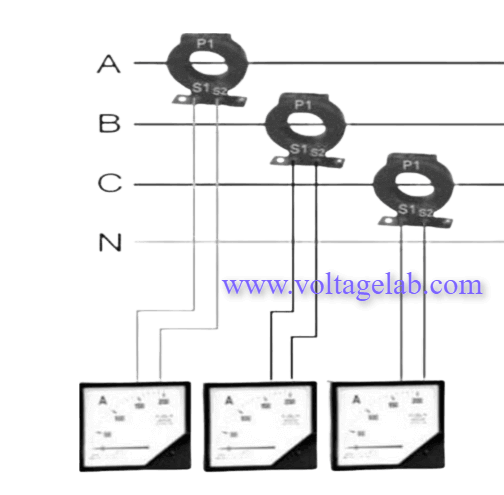
Follow the above wiring diagram diligently. This is 3 phase ct meter connection wiring diagram. There are three CTs connected with an ammeter individually. There are three incoming hot/live lines and a common neutral for all CTs. Normally, in the substation zone, the supply connection is not attached to the current transformer directly.
A huge current flow gained from higher potential is induced in the primary coil of the current transformer. Whenever the primary coil of CT senses higher current flow then it forwards the current in the secondary coil of CT.
For this reason, the secondary part of CT is always open in order to avoid short circuit problems due to high current flux density. After minimizing the tension of high flux concentration the ammeter begins to show the current reading.
What is the meaning of CT ratio 20:1 ?
It’s very simple. CT ratio 20:1 indicates that if the primary coil of CT is induced with 20 amps then the secondary part of CT will be induced with 1 amp. For high capacity substation, it can be narrated as 100:5.
Read More Interesting Articles
Shunt Trip Circuit Breaker Wiring Diagram
What is Relay? How To Draw a Simple Relay Wiring Diagram
Practice more with electrical quizzes
NEC · BS7671 · AS/NZS · CEC · DIN VDE
