



 Scan to install
Purpose
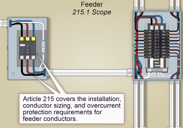
Article 215 of the National Electrical Code® (NEC®) establishes the requirements for the installation, sizing, and protection of feeder circuits — the conductors that carry power from the service equipment to branch circuit panels or distribution equipment.
Proper feeder design ensures safe power delivery without overheating or voltage drop.
Quick Answer
NEC Article 215 covers feeders: the circuit conductors between the service equipment (or a separately derived system) and the final branch-circuit overcurrent device. A feeder needs enough ampacity for the load it serves, and continuous loads are sized at 125%, so they never exceed 80% of the feeder rating.
Feeders also need overcurrent protection under Article 240, an equipment grounding conductor sized from Table 250.122, proper conductor identification, and ground-fault protection on large 3-phase, 4-wire systems of 1,000 A or more.
Key Concepts
- Definition (215.2) A feeder is all circuit conductors between the service equipment (or separately derived system) and the final branch circuit overcurrent device.
- Conductor Sizing (215.2(A))
- Feeders must have sufficient ampacity to handle the load served.
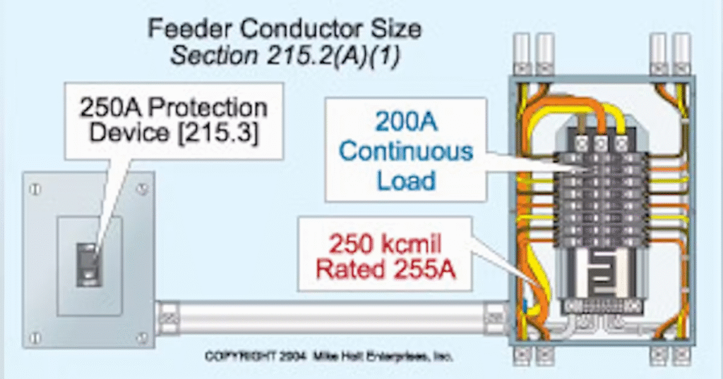
- Continuous loads must not exceed 80% of the feeder rating (sized at 125% of the continuous load).
- Apply voltage drop limits — feeders should not exceed 3% drop to maintain efficiency.
- Overcurrent Protection (215.3)
- Feeders require overcurrent devices rated to protect conductors per their ampacity (Article 240).
- Breakers or fuses must be located at the point where the feeder originates.
- Grounding & Bonding (215.6)
- Feeder equipment grounding conductors (EGCs) must be sized per Table 250.122.
- Grounded conductor (neutral) and EGC must be isolated in subpanels.
- Identification (215.12)
- Feeder conductors must be color-coded or labeled to distinguish ungrounded, grounded, and grounding conductors.
- Example:
- Black, red, blue — phase conductors
- White or gray — neutral
- Green or bare — equipment ground
- Multiple Feeders & Disconnects (215.5)
- Each feeder must have a main disconnecting means.
- If multiple feeders supply one area, they must be clearly marked to show their source.
- Ground-Fault Protection (215.10)
- Feeders supplying 1,000 A or more to 3-phase, 4-wire systems must include ground-fault protection.
- This protects large equipment and minimizes service interruptions.
⚙️ Key Takeaways
- Feeders carry large electrical loads — correct sizing and protection are critical.
- Always follow ampacity tables (310.16) and protection rules (240).
- Maintain clear identification, grounding, and disconnect labeling.
- Voltage drop and overcurrent protection are essential for system performance and safety.
Article 215 feeders FAQ
What is a feeder in the NEC?
A feeder is all the circuit conductors between the service equipment (or a separately derived system) and the final branch-circuit overcurrent device.
What is the 125% rule for feeders?
Continuous loads must not exceed 80% of the feeder rating, which means the feeder is sized at 125% of the continuous load (NEC 215.2(A)).
How is the feeder equipment grounding conductor sized?
Feeder equipment grounding conductors are sized per Table 250.122 (NEC 215.6).
When is ground-fault protection required on a feeder?
Feeders supplying 3-phase, 4-wire systems of 1,000 A or more must include ground-fault protection (NEC 215.10). Check 215.10 for the voltage conditions and exceptions that apply under your adopted edition.