

Wire Gauge (AWG) Chart for Electricians: Ampacity and Size
Wire gauge chart for copper and aluminum, 14 AWG to 500 kcmil: ampacity from NEC Table 310.16, diameter and resistance from Chapter 9 Table 8, and wire size by breaker.
NEC 250.90-250.102 Explained: Bonding on the Line & Load Side
NEC 250.90 through 250.102 explained section by section: the four bonding jumpers, Table 250.102(C)(1) vs Table 250.122, and when a locknut is not a bond.
100-Amp Sub-Panel Wire Size: NEC Feeder & Ground Sizing
A 100 amp sub panel needs 3 AWG copper or 1 AWG aluminum, a full-size neutral and an 8 AWG copper ground. NEC 215.2, Table 310.16 and 250.122 explained.
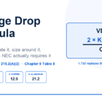
How to Calculate Voltage Drop: NEC Formula + Worked Examples
The voltage drop formula explained: VD = 2KIL/CM for single-phase, 1.732 for three-phase. Worked NEC examples, max run charts, and where 3% is mandatory.
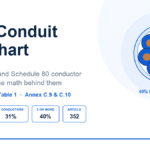
PVC Conduit Fill Chart: NEC Chapter 9 Limits for Schedule 40 & 80
PVC conduit fill chart for Schedule 40 and Schedule 80 with THHN. NEC Chapter 9 Table 1 percentages, Annex C counts, and the calculation for mixed wire sizes.
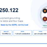
NEC 250.122 Explained: Sizing the Equipment Grounding Conductor
NEC 250.122 sizes the equipment grounding conductor from the breaker, not the load. Table 250.122 sizes, the 250.122(B) upsize rule, and the parallel trap.
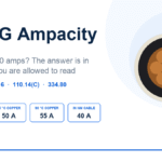
8 AWG Wire Ampacity: 40 A or 50 A? NEC 310.16 Explained
8 AWG ampacity is 40 A, 50 A or 55 A depending on which column of NEC Table 310.16 you are allowed to read. Here is how to pick the right one, with the 8 THHN and NM cable rules.
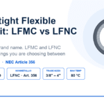
Liquid Tight vs Sealtite: LFMC vs LFNC Conduit Explained
Liquid tight vs sealtite explained: Sealtite is a brand, LFMC and LFNC are the two NEC wiring methods. Article 350 vs 356, fill, length limits and grounding.
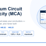
Minimum Circuit Ampacity (MCA) Explained for Electricians
Minimum circuit ampacity sizes your conductors, not your breaker. The NEC 440.32 and 440.33 formulas, MCA vs MOCP, and how to pick a wire from a nameplate MCA.
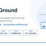
Ufer Ground (Concrete-Encased Electrode) Explained: NEC 250.52(A)(3)
Ufer ground explained: what NEC 250.52(A)(3) requires of a concrete-encased electrode, rebar vs 4 AWG copper, GEC sizing, and what disqualifies a footing.

NEC Code Book Editions: 2017 vs 2020 vs 2023 vs 2026 Differences
The NEC is updated every 3 years: 2017, 2020, 2023, 2026 (next: 2029). Key changes in each edition, which states use which, and which to study for your exam.
Proper Sizing of Conduits and Raceways. NEC Annex C.
NFPA 731 Section 4.6.3.12(2) clearly states that whenever raceways, conduits, or tubing are used (even for security systems), they must be sized in accordance...