


A Monostable Multivibrator Circuit, using a 555 Timer IC, is a practical electronic project to generate precise single pulses in response to an external trigger. This circuit is commonly used for applications like timers, pulse generators, and debounce switches. The 555 Timer operates in monostable mode, where it produces a single output pulse for a predefined time, which is controlled by external resistor and capacitor components. This article provides step-by-step instructions for building a Monostable Multivibrator Circuit and explains how to operate it efficiently.
This article demonstrates a Monostable Multivibrator Circuit using a 555 timer IC. Before reading about the Monostable Multivibrator Circuit, you can check out the Astable Multivibrator project.
Required Components
Study smarter with VoltageLab
Built for electricians, apprentices, and electrical engineers who want faster practice and better exam prep.
⭐️ Join thousands of electricians upgrading their skills
- Battery (6v-12v) – 1 piece
- 555 Timer – 1 piece
- Resistor (100k) – 1 piece
- Resistor (10k) – 1 piece
- Capacitor (4.7uF) – 1 piece
- Capacitor (0.01uF) – 1 piece
- Push Switch – 1 piece
- LED – 1 piece
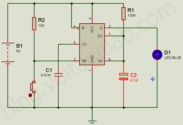
Procedure
In this circuit, a Monostable Multivibrator is created using a 555 timer.
Multivibrator:
A multivibrator is a type of circuit used to generate various types of non-sinusoidal waves such as square waves, sawtooth waves, and rectangular waves. There are different types of multivibrators, such as:
- Astable Multivibrator
- Monostable Multivibrator
- Bistable Multivibrator
By using these multivibrators, we can obtain different types of waves from the 555 timer’s output, allowing us to control the load in various ways.
Monostable Multivibrator
Here, the 555 timer operates in monostable mode, which controls the output by generating short pulses or small voltages at intervals.
For example, when a voltage is supplied to an LED through a push switch, the LED will light up when the switch is pressed. After a while, it will automatically turn off, or it can be turned off by pressing the switch again. The duration for which the LED stays lit depends on the resistor and capacitor values of the 555 timer.
Pass your electrical exam the first time
Practice real NEC exam questions with full code-referenced explanations and progress tracking — built for journeyman, master and apprentice exam prep.
Thousands of NEC practice questions with code-referenced answers
Precautions
- When connecting the component legs, do it carefully and slowly to avoid breaking them.
- Ensure all components are connected correctly when assembling the circuit.
- AC voltage should not be applied to the 555 timer.
- Do not apply a voltage higher than the specified voltage to the 555 timer.
Video
That’s it for today. If you face any issues while building the circuit, feel free to comment below.
Read More: Circuit diagram of Astable Circuit Diagram
FREE PRACTICE TOOL
Think you'd pass this on a real exam?
Test what you just read with instant-feedback quizzes built around real code questions — not generic trivia.
5
Code standards
10,000+
Active learners
100%
Free to start
Instant explanations on every answer, right or wrong
NEC, BS7671, AS/NZS, CEC, and DIN VDE covered
Bite-sized quizzes you can finish in 5 minutes
No signup required to try your first quiz
No account needed · Takes less than 2 minutes