
A ceiling fan is a crying need in our running lives. As electrical engineers, we have to know the ceiling fan speed control switch wiring diagram. In this article, I am going to discuss the ceiling fan speed control switch wiring diagram and simple implementation in our daily lives. Let’s discuss it.
How does a Ceiling Fan rotate?
Before going to details about ceiling fan speed control I want to explain how ceiling fan rotates in a nutshell. For a better realization of the function of the ceiling fan, you should have a clear concept of the induction motor. Let’s try to understand.
Take a magnet bar. Then let it hang around freely. Now tell me where it’s facing? The answer will be that it will always face north-south. This is because it wants to stay along with the Earth’s magnetic field (which is along the north-south).
This is a common characteristic of magnets. Every magnet wants to align itself with an external magnetic field. Now if I keep rotating the outer magnetic field without standing still, the magnet will also rotate to coincide with it.

This is basically the function of the motor. That is to say, the motor works through the action of two magnetic fields- the rotating magnetic field and the stationary magnetic field that follows the dynamic magnetic field.
Now, a question may arise in your mind, how can I create a rotating magnetic field? Let’s clear the confusion first.
How to create a rotating magnetic field?
The magnet can definitely be turned around. Another method is through the flow of electricity. Have you ever heard of the electromagnet?
Everyone knows that when electricity flows through a coil, a magnetic field is created around it.
The magnetic field that will be created if the DC current flows into the solenoid by twisting the wire is similar to the magnetic field of the magnet bar.
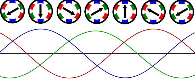
There are three live wires in the transmission and distribution lines. Although the same amount of electricity flows through these three live wires, there is some difference between them. The current flowing through each wire is at an angle of 120 degrees from the other.
So if you put a magnet in the middle this time, it will continue to follow this rotating magnetic field and rotate. Our motor was gone. Because the same poles of the magnetic field attract each other and the opposite poles repulse each other.
A mentioning fact is, single-phase supply can’t produce the rotating magnetic field. When a positive cycle comes, it creates a magnetic flux. But, in the negative cycle, it produces the same magnetic flux in opposite direction. As a result, the net magnetic force is zero. It can be compared with a real-life example. Suppose, two persons pull a rope with the same force in opposite direction. As a result, there is no movement of rope in this case. That’s why we use capacitors in ceiling fans for creating magnetic force and torque.
We can easily control the torque and speed by constructing a speed control switch. Let’s draw a ceiling fan speed control switch wiring diagram:
Ceiling Fan Speed Control Switch Wiring Diagram:

Ceiling Fan Speed Control Switch Types
There are two types of ceiling fan speed control switches. They are:
- Electrical Switch
- Electronic Switch
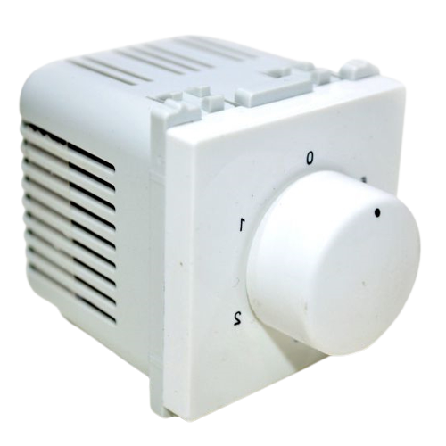
Electrical Switch
These regulators have variable resistances which are installed to reduce the voltage of the fan. When the voltage of the fan is reduced, the resistance heats up and the speed of the fan is also reduced due to the decrease in the power supply. But as a result of this, the electricity that is saved by reducing the voltage of the fan is converted into this resistance-mediated heat energy. That is why, by reducing the speed of the fan through this regulator, the power consumption is not much reduced.
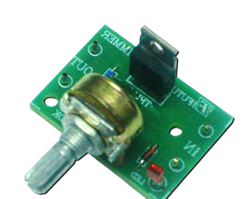
Electronic Speed Control Switch
In order to reduce the voltage of the fan, these regulators mainly contain the switching device triac. Here the gate signal controls the sine wave of the fan’s voltage and the speed of the fan is controlled by changing the RMS value of the voltage. These never get hot, so considerable electricity is saved when the fan moves at a low speed. Electronic regulators are generally about 40 percent more efficient than electric regulators.
Read More Articles
