We have already known about Bridge Rectifier With Capacitor Filter in our previous article. I am going to discuss another way to rectify an AC signal. This is center tap full wave rectifier with capacitor filter. What is center tap full wave rectifier? How it will rectify an AC signal. Let’s know the pros and cons of this topic.
What is Center Tap Full Wave Rectifier With Capacitor Filter?
The milestone of utilizing a rectifier is to convert AC signal to DC signal. But the device arrangements may be unique in this case. In the bridge full-wave rectifier circuit we use four diodes and arranged a bridge network for rectification purposes. But in this case, we use a center tap transformer and two diodes for the rectification process. Besides, there is a capacitive filter circuit for filtering the ripple quantity of the output signal.
Why it is Called Center Tapped?
Suppose, you have a fruit cake. You take a knife and cut the cake into two individual pieces through its center. This instance is comparable with a center-tapped transformer. There is a wire that is connected to the center of the secondary winding of the transformer. This acts as a neutral wire. In fact, there are two individual secondary voltages. Here you can compare the neutral wire with a knife, secondary winding with cake and the two individual voltages with two pieces of cake. How interesting fact! Have you ever thought in such a way? This is the basic reason why this transformer is called so.
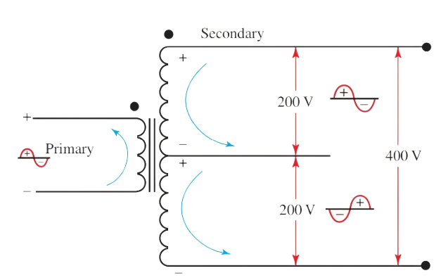
Look at the above picture. Here a short line is connected to the center of the secondary winding. If we measure voltage between half winding and neutral point the actual voltage will be 200V. So, as a result, the voltage will be 400V. Here 400 volts is divided into two individual and equal volts. After realizing the center tap transformer fact, I hope the center tap full wave rectifier action will be easier to you.
Necessary Instruments For Center Tap Full Wave Transformer With Capacitor Filter:
- Center tap transformer (Step down, 220/12 volt AC)
- Two Diodes (1N4003)
- Resistors (1K ohms)
- Capacitors (100 uF)
Circuit Operation of Center Tap Full Wave Transformer With Capacitor Filter:
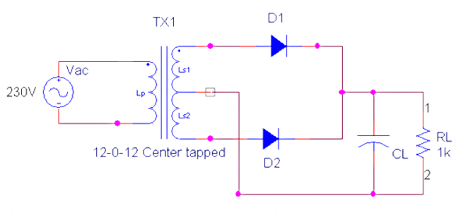
The circuit action of the center tap full-wave bridge rectifier with capacitor filter is similar to the bridge full-wave rectifier circuit. The difference is there are only two diodes and the bridge rectifier contains four diodes. Let’s see the action step by step.
Step 1:
When Positive Half Cycle Comes:
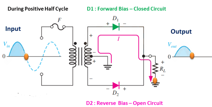
- When the positive half cycle comes Diode D1 becomes turned on and Diode D2 becomes turned off.
- Because the positive side of diode D1 gets positive peak of AC voltage and the positive side of Diode D2 gets negative peak.
- We all know that, a diode acts as a short circuit in forward bias and an open circuit in reverse bias.
- In this case, diode D1 acts as a short circuit and conducts electricity.
- On the contrary, diode D2 acts as an open circuit and doesn’t conduct electricity.
- This time the electricity flows from positive to negative terminal of the winding.
- Finally, we gained a rectified output across the load resistor.
Step 2:
When Negative Half Cycle Comes:
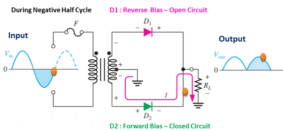
- When the negative half cycle comes Diode D2 becomes turned on and Diode D1 becomes turned off.
- Because the positive side of diode D2 gets positive peak of AC voltage and the positive side of Diode D1 gets negative peak.
- Here diode D2 acts as a short circuit and conducts electricity.
- On the contrary, diode D1 acts as an open circuit and doesn’t conduct electricity.
- This time the electricity flows from negative to positive terminal of the winding.
- Finally, we again gained a rectified output across the load resistor.
Final Output:
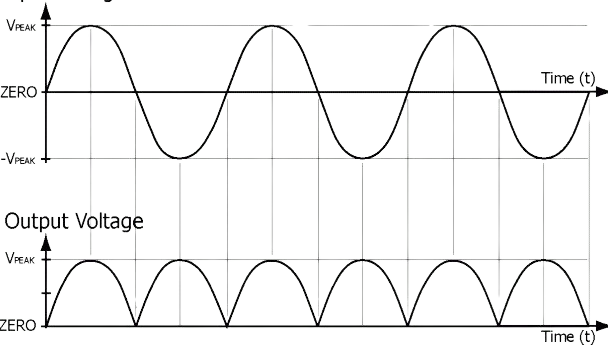
In the above picture, we can see rectified DC output. Does it seem really DC signal? No, actually the output isn’t pure DC. The rectified output bears a little ripple quantity. There is also an AC signal which ought to be filtered with a view to achieving pure DC output. This actually is like filtering sand from table salt when it is extracted from the water of the sea. Here we use a capacitive filter circuit for filtering purposes. You can compare the rectified output with table salt, ripple quantity with sand, and filter with the capacitor.
How does a Capacitive Circuit Filter The Ripple Quantity?
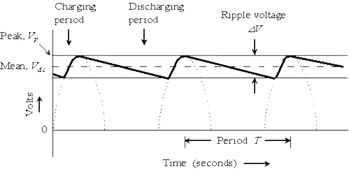
- Mr. Capacitor always likes AC to enter his heart. But Mr. Capacitor hates DC and blocks it to enter. How interesting!
- Suppose, the combined ac and dc signal wants to pass through the capacitor.
- Due to having null frequency DC can’t pass through the mind of Mr. Capacitor. Mr. Capacitor acts as an open circuit in this case.
- When AC falls into the romantic trap of Mr. Capacitor and gets filtered.
- Finally, we can acquire only DC output across the load.
- As we know capacitor is a bi-directional device. The charging current and discharging current flow in opposite directions to each other.
- When the capacitor starts to charge it opposes DC to flow and allows AC to pass through it.
- In discharging conditions, this process is also repeated.
- As a result, the rectified ripple output turns to a pure DC signal.
Read More Articles:


