

Have you heard about people with dual personalities? It’s very tough to handle this type of person who doesn’t bear a fixed manner. In our electrical technology, there is also a double standard character which is alternating current. But we have also arrangements with a view to rectifying this dual character. It’s a bridge rectifier. Today, I will discuss on bridge rectifier with a capacitor filter. Let’s discuss.
What is Bridge Rectifier?
Before going into detail about the bridge rectifier with capacitor filter I want to introduce the bridge rectifier first. In the above statement, you can assume about the bridge rectifier already. But I want to summarise this fact again. A bridge rectifier is a diode base circuit that converts alternating current to direct current. Four diodes are arranged here for rectifying purposes.
Study smarter with VoltageLab
Built for electricians, apprentices, and electrical engineers who want faster practice and better exam prep.
⭐️ Join thousands of electricians upgrading their skills
Necessary Instruments To Construct Bridge Rectifier With Capacitor Filter
- AC Power Supply (220 Volt power supply)
- Four Diodes ( 1N4003, for 220-volt peak voltage)
- Resistor (1K ohms)
- Capacitor (Electrolite Capacitor, 100 uF)
The function of The Bridge Rectifier Circuit With Filter Capacitor
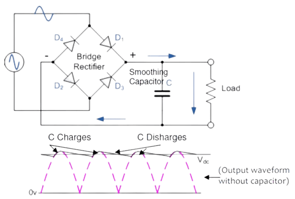
Look at the above circuit diagram. The AC signal is applied in the bridge rectifier circuit from the AC power supply. We already say that the AC signal has a dual character. It fluctuates between positive and negative cycles.
When Positive Half Cycle Comes:
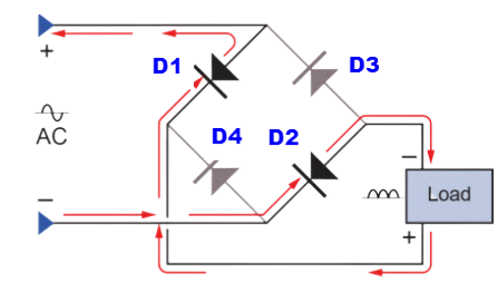
- In the beginning, the positive cycle comes, diodes D1 and D2 are forward biased and the rest of the two D3 and D4 are reversed biased.
- As we know, the diode acts as a short circuit in forward bias and an open circuit in reverse bias. Because diode internal resistance is so negligible.
- So, in forward bias, we can get out across the load. Besides, there is no current flow in the rest of the two diodes as they are in reverse bias.
When Negative Half Cycle Comes:
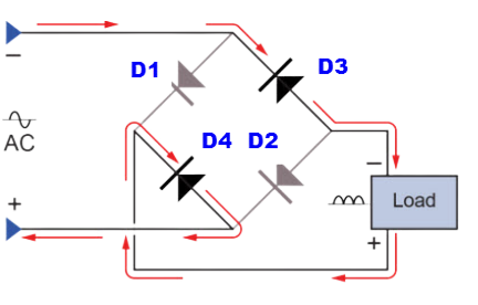
- When the negative half AC cycle comes, the D3 and D4 diodes are in forward bias and the rest of the two are in reverse bias.
- Similarly, they give DC output to the corresponding load.
- In these circumstances, diodes D1 and D2 don’t conduct current as they are in reverse bias.
- There is a shunt capacitor that is connected parallel with the load for filtering purpose.
How does Capacitor Act As Filter Circuit?
- The rectified output from the diode is not pure DC. Because AC character also exists here. But our milestone is to acquire pure DC output.
- So, you ought to utilize a capacitor for filtering the ripple quantity.
- We know that the capacitor blocks DC and allows AC to flow across the load. Because DC capacitor acts as an open circuit as DC has no frequency.
- For zero frequency capacitor has infinite reactance that obstructs DC signal to pass.
- On the contrary, the AC signal has a frequency.
- In fact, the capacitor bears average reactance and lets AC pass through the capacitor.
- In a positive half cycle, a capacitor gets charged and during the negative half cycle, the capacitor gets discharged.
- Through the charging and discharging process, the capacitor filters ripple quantity.
Why Full Wave Rectifier is Better Than Half Wave Rectifier?
- A full-wave rectifier is better than a half-wave rectifier. Because:
- Half-wave rectifier efficiency is 41% and full-wave rectifier efficiency is 81%
- In a full-wave rectifier, the peak value is doubled. But in a half-wave rectifier, the peak value is not doubled.
- The voltage regulation of a full-wave rectifier is better than a half-wave rectifier.
- The frequency is also doubled in a full-wave rectifier than a half-wave.
Why It’s Better To Use Bridge Rectifier In Lieu of Center Tapped Full Wave Rectifier?
- Maximum manufacturers prefer bridge rectifiers to center tap full-wave rectifiers. Because in center tap full wave rectifier we have to use a transformer which makes transformer so bulky.
- Besides, using a transformer the cost of a rectifier circuit becomes high comparatively.
- Moreover, the voltage regulation of the bridge rectifier is very smooth than the center tap rectifier.
Read More Articles
What does a Transistor do? Explain the Working Principle of a Transistor
Analog Technology vs Digital Technology | Evolution of technology
FREE PRACTICE TOOL
Think you'd pass this on a real exam?
Test what you just read with instant-feedback quizzes built around real code questions — not generic trivia.
5
Code standards
10,000+
Active learners
100%
Free to start
Instant explanations on every answer, right or wrong
NEC, BS7671, AS/NZS, CEC, and DIN VDE covered
Bite-sized quizzes you can finish in 5 minutes
No signup required to try your first quiz
No account needed · Takes less than 2 minutes
