


Have you heard about the shunt trip circuit breaker? How will we draw the shunt trip breaker wiring diagram? We are acquainted with a circuit breaker that protects our power system from unwanted faults such as a short circuit.
Quick Answer
Study smarter with VoltageLab
Built for electricians, apprentices, and electrical engineers who want faster practice and better exam prep.
⭐️ Join thousands of electricians upgrading their skills
A shunt trip breaker wiring diagram shows a circuit breaker whose internal shunt coil is wired to a separate control circuit. When a trip signal, such as a fire alarm relay or emergency stop, applies the coil’s rated voltage, the coil trips the breaker and opens the power circuit remotely.
The control voltage must match the shunt coil’s rating on the breaker label (for example 24 V DC or 120 V AC). The coil is short-time duty, so many designs use an auxiliary contact in the breaker to drop the coil out after it trips. After a trip, remove the signal and reset the breaker manually.
Electricity is more ferocious than the leopard. A few days back, a leopard fell in death due to the flow of electricity. So, it’s very essential to develop a protection system with a view to avoiding an unwanted accident. A shunt trip circuit breaker is a vital solution in these circumstances. Let’s know the function & shunt trip breaker wiring diagram in a simple manner.
What is shunt trip breaker?
This breaker is assembled with two basic parts:
- Shunt trip accessories
- Main circuit breaker part
Shunt trip accessories are attached to the main circuit breaker to protect the electrical system from any kind of undesired circumstances.
So, we can say that A shunt trip is an essential part of a circuit breaker that mechanically trips the breaker when power is applied to the shunt trip terminals. Now a question may arise, how do shunt trips consume power?
Study smarter with VoltageLab
Built for electricians, apprentices, and electrical engineers who want faster practice and better exam prep.
Join thousands of electricians upgrading their skills
How Do Shunt Trip Breakers Consume Power?
Shunt trip consumes power from an external power source. It doesn’t consume power from the circuit breaker cascaded with it.
How does Shunt Coil work?
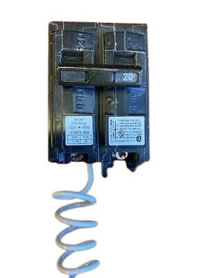
A shunt coil is used in the shunt trip breaker. It is used before the arrival of the relay. This shunt coil contains an electromagnet that is energized by an external power source and produces a magnetic field. There is a moveable bar that is attached to a spring for physical movement.
The shunt trip moveable bar hits the tripping point of the circuit breaker internally and the breaker becomes off. In the MCCB circuit breaker, the tripping point is named “push to the trip”. While switching on the breaker and pushing this button the breaker becomes switched off and trip due to pushing this button. The shunt trip coil rod pushes this point internally when the shunt coil is operated. This will be more clear to u when I will discuss the shunt trip breaker wiring diagram.
Shunt Trip Breaker Wiring Diagram and Connection Proceedure
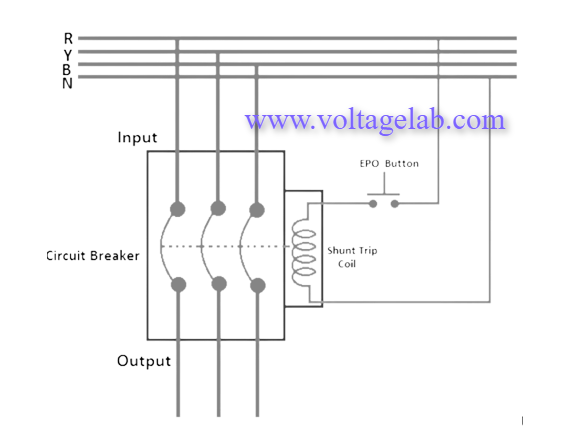
Please look at the above shunt trip breaker wiring diagram. A mentioning fact is that here the tripping coil in the MCCB is rated for 230V single-phase supply. Let’s discuss the connection procedure:
- At first we have to connect the neutral wire of the power supply to anyone terminal of the shunt trip coil. If its terminals are identified, then connect to the neutral terminal.
- Then we have to connect anyone terminal of the EPO (Emergency Push Off) button to any one phase of the power supply from the output of the MCCB.
- Finally, the rest terminal of the shunt trip coil should be connected with another terminal of EPO button. Connect another terminal of the EPO button.
- If the operating volt of the shunt coil is 220 volt, then we require to supply 220 volts to the shunt coil to operate or trip the breaker in a faulty time. So, our neutral will be connected directly to the shunt tripping coil, and the live line will be connected to the coil on another side through the EPO push-button switch normally open contacts.
How Shunt Trip Breaker Differs From Regular Circuit Breaker?
- Ground fault breakers monitor the current on the neutral wire. On the other hand, shunt trip breakers can be tripped after energizing the shunt coil.
- Regular breakers utilize a relay for tripping purposes but shunt trip coil breakers use a shunt coil in this regard.
- GFCI (Ground Fault Circuit Interrupter) can’t be connected to a control circuit but shunt trip breaker is connected to control circuit.
Read More Articles
Introduction To Ice Cube Relay And Its Wiring Diagram
Discussion about Load Break Switch
Frequently Asked Questions
What is a shunt trip breaker used for?
A shunt trip breaker lets an external signal open the circuit remotely. Typical uses are tying a breaker to a fire alarm, emergency-stop button or building control system so the supply can be shut off from a safe location.
How do you wire a shunt trip breaker?
Wire the control voltage source through the initiating contact (the switch, relay or alarm output) to the two shunt coil terminals on the breaker. The main line and load terminals are wired like a normal breaker. Use the terminal markings and coil voltage given in the breaker manufacturer’s instructions.
Does a shunt trip breaker need a separate power supply?
It needs a control voltage to energise the shunt coil. That can come from a separate control supply, or from a source chosen to stay live when you need the breaker to trip. The voltage must match the coil rating on the breaker.
FREE PRACTICE TOOL
Think you'd pass this on a real exam?
Test what you just read with instant-feedback quizzes built around real code questions — not generic trivia.
5
Code standards
10,000+
Active learners
100%
Free to start
Instant explanations on every answer, right or wrong
NEC, BS7671, AS/NZS, CEC, and DIN VDE covered
Bite-sized quizzes you can finish in 5 minutes
No signup required to try your first quiz
No account needed · Takes less than 2 minutes