

Would you be able to rotate a motor forward and reverse direction for a particular time? For this action, you have to acquire a clear conception of the forward-reverse control wiring diagram. Let’s discuss this topic today. Hope you will enjoy it.
Why We Rotate a Motor in Forward-Reverse Direction?
The motor is a crucial part of an industry. All kinds of mechanical works are being done by the motor. Because we know the motor can convert electrical energy to mechanical energy. Let’s give a nice instance. We use tower cranes in the industry. Especially, it is seen to utilize more in sea-port with a view to lifting heavy loads or containers.
Study smarter with VoltageLab
Built for electricians, apprentices, and electrical engineers who want faster practice and better exam prep.
⭐️ Join thousands of electricians upgrading their skills
So, the tower crane can move in any direction. That’s why the motor has to rotate clockwise or anti-clockwise with assigning angle in the program loaded in PLC or any kind of the computerized control system. Now, we are going to discuss the forward-reverse control wiring diagram.
Required Instruments For Motor Forward-Reverse Control
- Magnetic Contactor
- Miniature Circuit Breaker
- RYB (Three Phase Lines)
- Overload Relay
- Three Phase Motor
- On-off Push Switches
Motor forward-reverse control wiring diagram
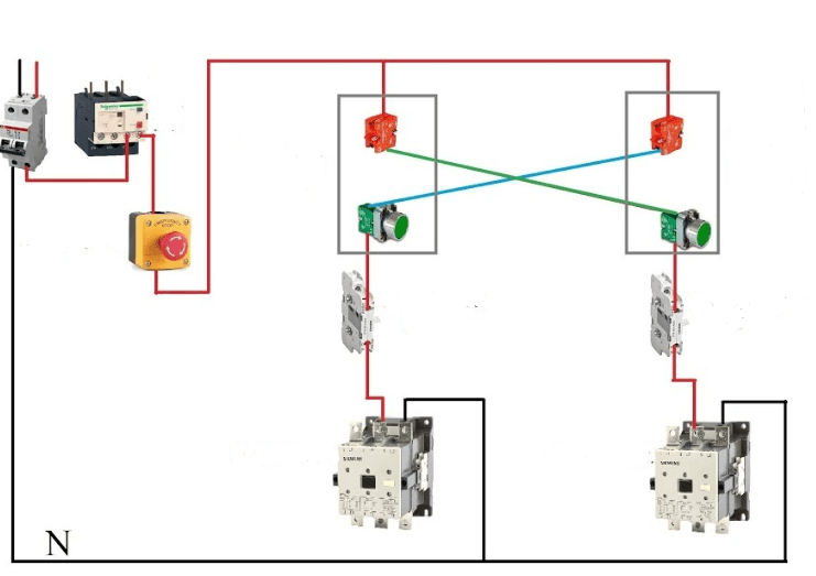
In the above-mentioned diagram is the motor forward-reverse control wiring diagram. Basically, it’s a timer-based automatic reverse forward system. Here we use two magnetic contactors. One magnetic contactor is used for forward and another is for the reverse direction.
An MCB (Miniature Circuit Breaker) is used for a 220-volt power supply. The miniature circuit breaker output is entered into the NO (Normally Open) contact. When the breaker is activated, then the NO contact of the push switch becomes close and delivers power to the timer coil and the forward magnetic contactor respectively. The forward switch on the motor and the motor starts to rotate in forward direction.
But this forward rotation will not be continue for a long time. A fixed time is set in the timer. Suppose, you set 15 seconds on the timer. But what will be happened after 15 seconds?
After 15 seconds the forward magnetic contactor will be turned off and the reverse magnetic contactor will be turned on. Then the second timer will count 15 seconds again. The motor began to rotate in the reverse direction for 15 seconds.
This is the basic operation of an automatic timer-based forward reverse wiring diagram. This can also be done manually. That means you can do this without a timer. You can also do this with two push switches.
Motor Forward Reverse Control Circuit
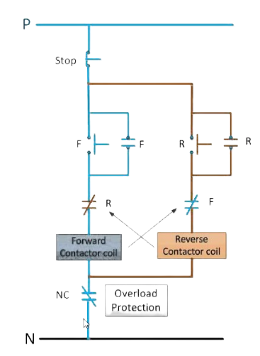
Let’s see the control circuit of the motor forward reverse action. Because in an automation system you have to observe the controlling diagram with a view to realizing the basic operation clearly.
There are two push switch contacts. One is for on push and another is for the off push. When the NO contacts of push switches get power supply then their NO contacts become close. After power consumption, the switching action will begin. A mentioning fact that the switch contact should be latched with a view to holding the power supply in spite of withdrawing the pressure from the push switch.
There are two magnetic contactors. One is for forward action and another is for reverse action. Look at the above diagram attentively. An NC contact of the reverse magnetic contactor is interlocked with the forward magnetic contactor. Similarly, an NC contact of forward magnetic contactor is interlocked with the reverse magnetic contactor.
Here a question will be arisen, why NC contacts are interlocked here?
When the forward magnetic contactor will be turned on then the reverse magnetic contactor will be turned off. Again, when the reverse magnetic contactor will be turned on then the forward magnetic contactor will be turned off. That’s why we apply an interlocking system here.
For a more clear assumption, I want to give you an instance. Suppose, you are talking with your friend over the telephone. When your friend talks, you have to keep silent. On the contrary, when you will talk, your friend ought to keep silent.
On the other hand, there is an NC contact of overload relay for overload protection. When the motor is overloaded then the overload relay turns on and protects motor winding from short circuit incident.
Read More Articles
What is Cogging in Induction Motor
The Story of Motor and Generator Excitation System
Practice more with electrical quizzes
NEC · BS7671 · AS/NZS · CEC · DIN VDE
