


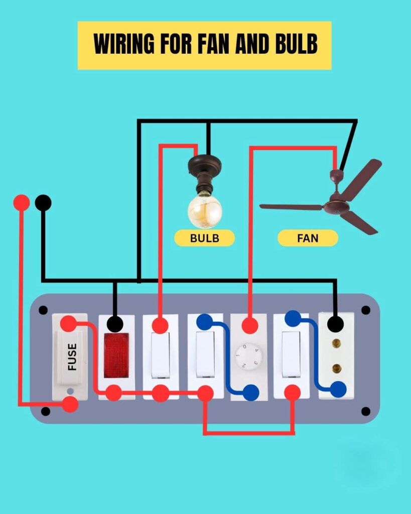
This diagram shows the basic electrical wiring for controlling a fan and bulb using separate switches. It’s a simple and essential household circuit that helps you understand how power flows through switches to operate electrical loads safely.
Key Components:
- Fuse: Provides circuit protection from overloads or short circuits.
- Switches: Control the fan and bulb individually.
- Fan Regulator: Adjusts the fan speed.
- Indicator Light: Shows when the power is ON.
Working Principle:
The phase wire passes through the fuse and individual switches before reaching the fan and bulb. The neutral wire completes the circuit back to the supply, ensuring both devices can operate independently and safely.
Study smarter with VoltageLab
Built for electricians, apprentices, and electrical engineers who want faster practice and better exam prep.
⭐️ Join thousands of electricians upgrading their skills
⚡ Tip: Always ensure connections are tight and insulated properly to prevent short circuits.
FREE PRACTICE TOOL
Think you'd pass this on a real exam?
Test what you just read with instant-feedback quizzes built around real code questions — not generic trivia.
5
Code standards
10,000+
Active learners
100%
Free to start
Instant explanations on every answer, right or wrong
NEC, BS7671, AS/NZS, CEC, and DIN VDE covered
Bite-sized quizzes you can finish in 5 minutes
No signup required to try your first quiz
No account needed · Takes less than 2 minutes