


An electrical gutter — formally called an auxiliary gutter in the NEC — is one of those items electricians run into constantly on commercial and industrial jobs but rarely look up the code on. That’s a problem, because the rules for auxiliary gutters are specific: they aren’t conduit, they aren’t wireways, and they aren’t junction boxes. NEC Article 366 gives them their own fill limitation and a conductor derating threshold that works very differently from the conduit rules you already know.
This guide covers NEC Article 366 in full: the definition and permitted uses of auxiliary gutters, what they can’t be used for, the 20% fill rule and how to calculate it, the 30-conductor ampacity adjustment threshold, busbar ampacity limits, auxiliary gutters vs. wireways, and a complete worked sizing example.
Study smarter with VoltageLab
Built for electricians, apprentices, and electrical engineers who want faster practice and better exam prep.
⭐️ Join thousands of electricians upgrading their skills
Quick Reference: Auxiliary Gutter Numbers
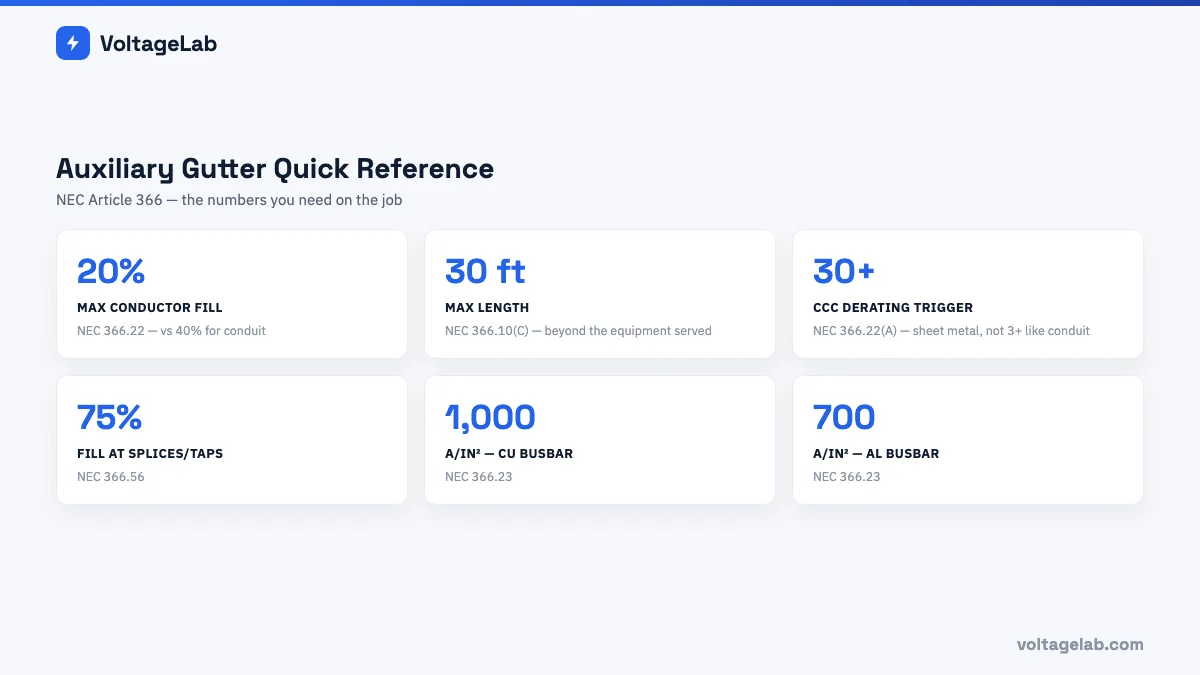
Before the deep dive, here are the numbers that matter most on the job — bookmark this section.
What Is an Auxiliary Gutter?
NEC Article 100 (2023 edition) defines an auxiliary gutter as: “An enclosure used to supplement wiring spaces at meter centers, distribution centers, switchgear, switchboards, and similar points of wiring systems. The enclosure has hinged or removable covers for housing and protecting electrical wires, cable, and busbars. The enclosure is designed for conductors to be laid or set in place after the enclosure has been installed as a complete system.”
The three critical words in that definition are “supplement wiring spaces.” An auxiliary gutter isn’t a general raceway between two distant points — it’s a supplementary enclosure used where the space inside a panel, switchboard, or similar equipment can’t fit all the conductors that need to enter, leave, or be spliced at that point. Think of it as an add-on workspace attached to or adjacent to electrical equipment.
What an auxiliary gutter looks like in the field: a rectangular sheet metal (or nonmetallic) enclosure with a hinged or removable cover, typically 4×4, 6×6, or 8×8 inches in cross-section, mounted directly to or adjacent to a panelboard, switchboard, or distribution center. Conductors from multiple conduits entering a distribution panel may land in the auxiliary gutter first, where they get organized and spliced before entering the equipment.
Two types defined in NEC Article 366 (2023 edition):
- Metal auxiliary gutter: a sheet metal enclosure — the most common type in commercial and industrial work
- Nonmetallic auxiliary gutter: a listed nonmetallic enclosure — typically used in corrosive environments or where grounding continuity through a metal gutter isn’t desired
Permitted Uses — NEC 366.10
Metal Auxiliary Gutters (NEC 366.10(A))
Sheet metal auxiliary gutters are permitted for:
FREE PRACTICE TOOL
Think you'd pass this on a real exam?
Test what you just read with instant-feedback quizzes built around real code questions — not generic trivia.
5
Code standards
10,000+
Active learners
100%
Free to start
Instant explanations on every answer, right or wrong
NEC, BS7671, AS/NZS, CEC, and DIN VDE covered
Bite-sized quizzes you can finish in 5 minutes
No signup required to try your first quiz
No account needed · Takes less than 2 minutes
- Indoor and outdoor use: metal auxiliary gutters may be used indoors and outdoors, provided outdoor installations use listed fittings suitable for wet locations
- Extending enclosures: used to extend the wiring space of meters, distribution centers, switchboards, switchgear, and similar equipment where the internal wiring space is insufficient
- Elevator wiring (NEC 366.10(A)(2)): metal auxiliary gutters may be used in connection with elevator wiring — see NEC 620.35 for the specific rules, which exempt elevator auxiliary gutters from the 30-foot length limit
Nonmetallic Auxiliary Gutters (NEC 366.10(B))
Nonmetallic auxiliary gutters have the same general use permissions as metal auxiliary gutters, with additional restrictions:
- Must be listed for use indoors where exposed to sunlight, and identified as sunlight-resistant where installed outdoors in sunlit locations
- Not permitted where subject to physical damage unless listed for that condition
- Where exposed to chemicals or vapors, must be identified for that application
Uses Not Permitted — NEC 366.12
NEC 366.12 establishes two critical limitations on auxiliary gutters:
- Length limitation — maximum 30 feet (NEC 366.10(C)): auxiliary gutters can’t extend more than 30 feet beyond the equipment they supplement. This reinforces the “auxiliary” nature of the enclosure — it isn’t intended as a long-distance raceway. Exception: auxiliary gutters used in elevator installations are exempt from the 30-foot length limit (NEC 620.35).
- Not a substitute for general raceways: auxiliary gutters aren’t permitted as a general wiring method between two separate pieces of equipment that aren’t in close proximity. An auxiliary gutter running 50 feet between two panels in different rooms isn’t a compliant installation — a conduit or wireway is required.
The 30-foot limit is the single most commonly violated auxiliary gutter rule in commercial construction. Installers who find auxiliary gutters convenient sometimes extend them past the equipment-supplement function — which is a code violation regardless of whether the fill percentage is met.
Fill Limitation — NEC 366.22: The 20% Rule
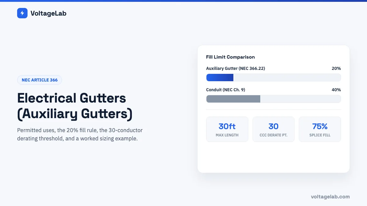
The fill limitation for auxiliary gutters is significantly more restrictive than the 40% fill used for conduit. NEC 366.22 limits conductor fill in both metal and nonmetallic auxiliary gutters to 20% of the interior cross-sectional area at any cross section.
Maximum conductor area = Interior cross-sectional area × 20%
Why 20% and not 40%: auxiliary gutters aren’t pull enclosures like conduit — conductors are laid in from above or set in place, not pulled through under tension. The 20% limit leaves room for conductors to lay without excessive bending, allows for heat dissipation, and keeps the gutter workable when the cover comes off for maintenance and modifications.
What counts toward the 20%: the cross-sectional areas of all conductors at any cross section of the gutter. Use NEC Chapter 9, Table 5 for insulated conductor areas — the same table used for conduit fill calculations. The EGC counts toward fill, same as conduit.
Fill Calculation Method
- Determine the internal cross-sectional area of the gutter (width × height for rectangular gutters)
- Calculate 20% of that area: maximum conductor area = internal area × 0.20
- Sum the cross-sectional areas of all conductors at the most densely filled cross section of the gutter (from NEC Chapter 9, Table 5)
- Total conductor area must not exceed the maximum conductor area
Worked Sizing Example
Scenario: a 6 × 6 inch sheet metal auxiliary gutter serves a distribution panel. At its most densely filled point, 18 conductors of 3/0 AWG THWN copper pass through. Is this within the 20% fill limit? (3/0 AWG THWN area from NEC Chapter 9, Table 5 = 0.2679 in² per conductor)
| Step | Calculation | Result |
|---|---|---|
| 1 | Internal cross-sectional area: 6 in × 6 in | 36 in² |
| 2 | Maximum conductor area: 36 × 20% | 7.2 in² |
| 3 | Total conductor area: 18 × 0.2679 in² | 4.82 in² |
| 4 | 4.82 in² ≤ 7.2 in²? | ✅ Yes — within 20% fill limit |
Maximum conductors of 3/0 AWG THWN in this gutter: 7.2 in² ÷ 0.2679 in² = 26.9 → maximum 26 conductors of this size.
💡 Get step-by-step help with gutter and conduit fill math.
VoltageLab’s AI Study Coach walks through fill calculations exactly like the one above — with explanations, not just answers — so 20% gutter fill and 40% conduit fill stop getting mixed up on the job or on the exam.
Study smarter with VoltageLab
Built for electricians, apprentices, and electrical engineers who want faster practice and better exam prep.
⭐️ Join thousands of electricians upgrading their skills
The 30-Conductor Threshold — NEC 366.22(A) Ampacity Adjustment
This is the rule that surprises the most electricians — particularly those who know the conduit derating rule well and assume auxiliary gutters work the same way.
NEC 366.22(A) states that where the number of current-carrying conductors in a sheet metal auxiliary gutter exceeds 30 at any cross section, the ampacity of each conductor must be adjusted per NEC Table 310.15(C)(1) — the same derating table used for conduit.
The critical difference from conduit derating:
| Feature | Conduit (NEC Table 310.15(C)(1)) | Sheet Metal Auxiliary Gutter (NEC 366.22(A)) |
|---|---|---|
| Derating triggered when | More than 3 current-carrying conductors | More than 30 current-carrying conductors at any cross section |
| Derating table | NEC Table 310.15(C)(1) | NEC Table 310.15(C)(1) (same table) |
| EGC counted? | No | No — only current-carrying conductors counted for derating |
| Neutral counted? | Only if carrying harmonic current | Same — balanced neutral on 3-phase system not counted |
Why the threshold is 30, not 3: auxiliary gutters are open enclosures with removable covers — heat dissipation from the conductors is much better in an open trough than in a sealed conduit. The NEC acknowledges this by setting the derating threshold at 30 current-carrying conductors rather than 3. In practice, most auxiliary gutter installations in commercial and industrial work never reach 30 current-carrying conductors at any single cross section, so derating is rarely required.
For nonmetallic auxiliary gutters (NEC 366.22(B)): the standard conduit derating rules from NEC Table 310.15(C)(1) apply at the normal thresholds (more than 3 CCC) up to and including the 20% fill limit. Nonmetallic gutters don’t get the 30-conductor exemption — they derate like conduit from 4+ current-carrying conductors.
The 75% Splices and Taps Rule — NEC 366.56
NEC 366.56 limits the space occupied by splices and taps within an auxiliary gutter. Splices, taps, and conductors combined must not fill more than 75% of the interior cross-sectional area at any point where splices or taps are made.
Note the two separate fill limits:
- Conductors only (no splices/taps): 20% maximum (NEC 366.22)
- At any point with splices or taps (conductors + splice/tap volume): 75% maximum (NEC 366.56)
The 75% limit at splice points is more permissive than the 20% conductor fill because splices and taps are discrete, localized bulges in the gutter — not a continuous increase in conductor density along the entire run. The 75% limit leaves room to work when making or maintaining connections inside the gutter.
Busbar Ampacity Limits — NEC 366.23
Auxiliary gutters sometimes contain busbars (copper or aluminum bars) instead of insulated conductors. NEC 366.23 limits the continuous current carried by bare metal bars in sheet metal auxiliary gutters:
| Material | Maximum Continuous Current per Unit Area |
|---|---|
| Bare copper bars | 1,000 A/in² (1.55 A/mm²) of cross-sectional area |
| Bare aluminum bars | 700 A/in² (1.09 A/mm²) of cross-sectional area |
Example: a bare copper busbar in a sheet metal auxiliary gutter is 1/4 inch × 2 inches in cross-section. What’s its maximum continuous current rating?
Cross-sectional area = 0.25 in × 2.0 in = 0.5 in²
Maximum continuous current = 0.5 in² × 1,000 A/in² = 500A
Auxiliary Gutter vs. Wireway — Key Distinctions
Auxiliary gutters and wireways look nearly identical in the field — both are rectangular metal enclosures with removable covers. The distinction matters because they’re governed by different NEC articles with different permitted uses and fill rules.
| Feature | Auxiliary Gutter (NEC Article 366) | Metal Wireway (NEC Article 376) |
|---|---|---|
| Defined purpose | Supplement wiring space at equipment — auxiliary only | General raceway — enclosed channel for conductors between points |
| Maximum length | 30 feet beyond the equipment it supplements | No specific length limit in NEC Article 376 |
| Where used | At or adjacent to distribution equipment | Between equipment as a raceway; in exposed locations |
| Fill limitation | 20% of cross-sectional area | 20% of cross-sectional area (same fill rule) |
| Conductor derating threshold | More than 30 CCC (sheet metal) | More than 30 CCC (same threshold for metal wireways) |
| Splices and taps permitted? | Yes — up to 75% at splice points | Yes — up to 75% at splice points (same rule) |
| Governing NEC Article | Article 366 | Article 376 |
Practical test: if the enclosure connects two pieces of equipment separated by more than 30 feet, or serves as the primary raceway between remote equipment, it must be a wireway (Article 376), not an auxiliary gutter (Article 366). If it extends the wiring space of a distribution panel, switchboard, or meter center and stays within 30 feet of that equipment, an auxiliary gutter is the correct designation.
Construction and Installation Requirements
Grounding and Bonding (NEC 366.60)
Metal auxiliary gutters must be grounded and bonded per NEC Article 250. The metal gutter must be bonded to the equipment grounding conductor system — typically through mechanical connection to the grounded enclosure of the distribution equipment it serves. If you’re unclear on the difference between grounding and bonding hardware in this context, see our guide to grounding vs. bonding bushings under the NEC.
Expansion Fittings (NEC 366.44)
Where temperature changes will cause the auxiliary gutter to expand or contract more than 0.25 inches (6 mm), expansion fittings must be provided. This applies to outdoor installations and indoor installations in areas with wide temperature swings. Auxiliary gutters installed across expansion joints in a building structure also require expansion fittings.
Listing Requirement
Auxiliary gutters and associated fittings must be listed. Generic sheet metal channel isn’t the same as a listed auxiliary gutter — use products specifically listed for use as auxiliary gutters per NEC 366.6.
Cover and Accessibility
Auxiliary gutters must have hinged or removable covers that provide access to the conductors inside. The cover must be secured against accidental opening but accessible for maintenance and modification. Conductors inside must be protected from physical damage.
Bending Space
The gutter must provide sufficient bending space for the conductors at all turning points. For conductors entering or leaving an auxiliary gutter, the bending radius requirements from NEC Table 312.6(A) apply — which can significantly affect the required gutter dimensions for large conductors. For example, a 3/0 AWG conductor requires a minimum of 4 inches of bending space at a 90° turn.
Conclusion
Auxiliary gutters are a specific-purpose enclosure governed by NEC Article 366 — designed to supplement wiring space at distribution equipment, not to serve as a general raceway. Three rules to apply on every auxiliary gutter installation:
- 20% fill for conductors — significantly more restrictive than conduit. Use NEC Chapter 9, Table 5 areas and stay at or below 20% of the gutter’s internal cross-sectional area.
- 30 feet maximum — auxiliary gutters can’t extend more than 30 feet beyond the equipment they serve. Beyond 30 feet, use a wireway or conduit.
- Derating at 30+ current-carrying conductors (sheet metal gutters) — not at 3+ like conduit. The 30-conductor threshold reflects the superior heat dissipation of the open gutter design vs. sealed conduit.
For sizing conduit runs connected to auxiliary gutters, use our Conduit Fill Calculator. For sizing pull boxes at the ends of conduit runs with large conductors, see Pull Box & Junction Box Sizing: NEC Rules with Chart. And for the full picture on bonding this equipment correctly, check our Grounding vs. Bonding Bushings guide.
📱 The electrical reference and study app built for working electricians.
VoltageLab puts Wiring Guides, an interactive circuit simulator, unlimited AI-generated practice questions, and flashcards in your pocket — so code rules like NEC Article 366 actually stick. Built for working electricians and apprentices. Free on iOS and Android.
Or see everything the app covers on the VoltageLab app page.
Frequently Asked Questions
What is an electrical gutter (auxiliary gutter) used for?
An auxiliary gutter is an enclosure used to supplement — extend — the wiring space at distribution equipment such as panelboards, switchboards, switchgear, and meter centers. It provides additional room to organize, splice, and route conductors that won’t fit within the equipment’s own internal wiring space. It’s not a general-purpose raceway — it must be installed at or adjacent to the equipment it serves and is limited to 30 feet in length beyond that equipment per NEC 366.10(C).
What is the fill limit for an auxiliary gutter?
Per NEC 366.22, the conductors in an auxiliary gutter can’t exceed 20% of the gutter’s interior cross-sectional area at any cross section. This applies to both sheet metal and nonmetallic auxiliary gutters. At any location where splices or taps are made, the total space occupied by conductors, splices, and taps combined can’t exceed 75% of the interior cross-sectional area per NEC 366.56. Use NEC Chapter 9, Table 5 for the cross-sectional areas of insulated conductors.
When does ampacity derating apply to auxiliary gutters?
For sheet metal auxiliary gutters, the ampacity adjustment factors from NEC Table 310.15(C)(1) apply only when there are more than 30 current-carrying conductors at any cross section, per NEC 366.22(A). That’s significantly different from conduit, where derating begins at more than 3 current-carrying conductors. For nonmetallic auxiliary gutters, the standard conduit derating rules apply from the normal thresholds per NEC 366.22(B) — the 30-conductor exemption doesn’t apply to nonmetallic gutters.
What is the difference between an auxiliary gutter and a wireway?
Both are rectangular metal enclosures with removable covers that contain conductors. The key difference is purpose and length: an auxiliary gutter (NEC Article 366) supplements wiring space at specific equipment and can’t extend more than 30 feet beyond that equipment. A metal wireway (NEC Article 376) is a general-purpose raceway used to route conductors between equipment with no length limit. Both share the same 20% fill rule and the same 30-conductor derating threshold. If the enclosure runs more than 30 feet or serves as the primary raceway between two remote pieces of equipment, it must be classified and installed as a wireway.
What is the busbar ampacity limit in an auxiliary gutter?
Per NEC 366.23, bare copper bars in sheet metal auxiliary gutters are limited to 1,000 amperes per square inch (1.55 A/mm²) of cross-sectional area continuously. Bare aluminum bars are limited to 700 amperes per square inch (1.09 A/mm²). To calculate the maximum current for a specific busbar, multiply its cross-sectional area in square inches by 1,000 (copper) or 700 (aluminum). For example, a 1/4″ × 2″ copper busbar has a cross-section of 0.5 in², giving a maximum continuous current of 500A.
FREE PRACTICE TOOL
Think you'd pass this on a real exam?
Test what you just read with instant-feedback quizzes built around real code questions — not generic trivia.
5
Code standards
10,000+
Active learners
100%
Free to start
Instant explanations on every answer, right or wrong
NEC, BS7671, AS/NZS, CEC, and DIN VDE covered
Bite-sized quizzes you can finish in 5 minutes
No signup required to try your first quiz
No account needed · Takes less than 2 minutes