


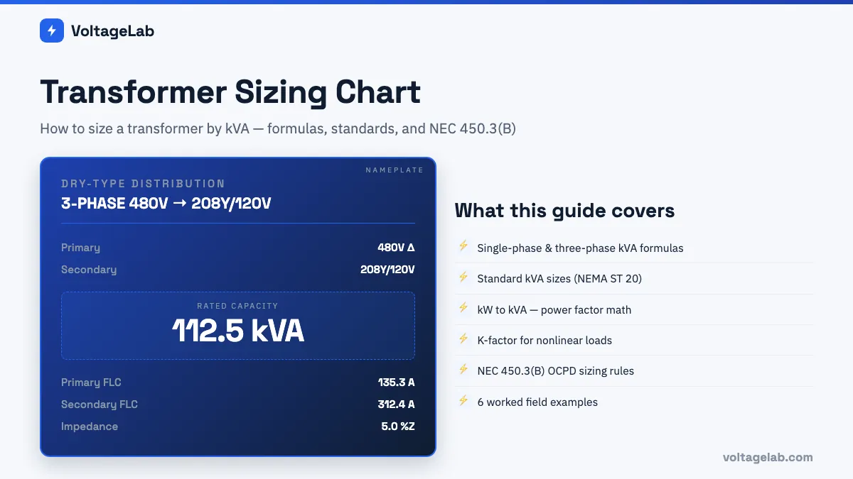
Transformer sizing starts with one question: how much apparent power (kVA) does the load need, and does the transformer you are selecting meet or exceed that requirement? Get the kVA right, and you can correctly size the primary and secondary conductors, select the overcurrent protective devices per NEC Article 450.3, and specify a transformer that handles the load without running hot or tripping nuisance overloads.
Quick Answer
Study smarter with VoltageLab
Built for electricians, apprentices, and electrical engineers who want faster practice and better exam prep.
⭐️ Join thousands of electricians upgrading their skills
To size a transformer, calculate the load in kVA, add margin, and round up to the next standard size. Single-phase kVA = V × I ÷ 1,000. Three-phase kVA = 1.732 × line-to-line V × line current ÷ 1,000. If the load is in kW, divide by the power factor first.
Standard sizes include 15, 25, 37.5, 50, 75 and 100 kVA single-phase, and 30, 45, 75, 112.5, 150, 225 and 300 kVA three-phase. Continuous loads are sized at 125%. For a quick answer, use the free transformer sizing calculator.
This guide covers the complete transformer sizing process — the kVA formulas for single-phase and three-phase systems, the standard kVA sizes to select from, how power factor affects sizing, the K-factor transformer requirement for nonlinear loads, the NEC 450.3(B) OCPD sizing rules for both primary and secondary protection, and six worked examples covering the most common field scenarios.
- The kVA sizing formulas — single-phase and three-phase
- Standard transformer kVA sizes — the complete selection chart
- kW to kVA conversion — the power factor relationship
- How much margin to add and why
- K-factor transformers — when standard dry-type is not enough
- Full-load current from kVA — primary and secondary
- NEC 450.3(B) — OCPD sizing for transformers ≤1,000V
- Six worked sizing examples
The kVA Sizing Formulas
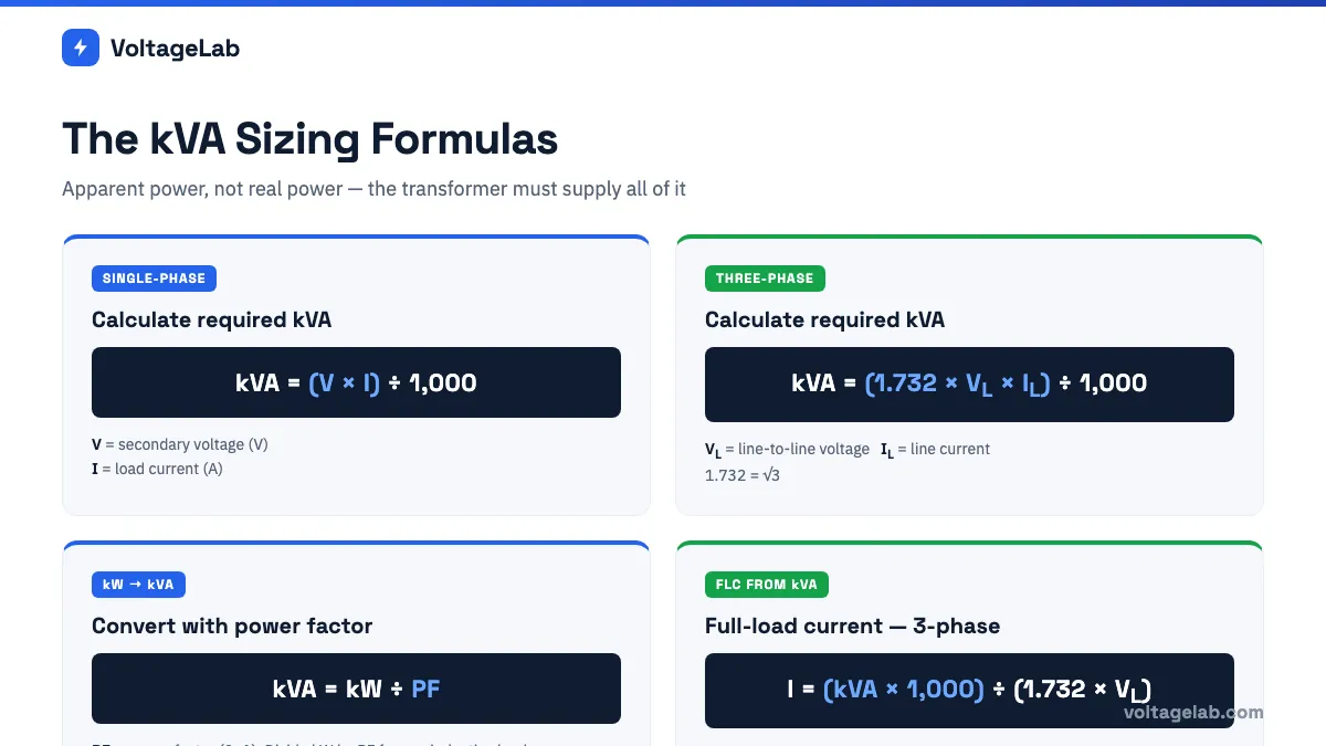
A transformer is rated in kVA (kilovolt-amperes) — apparent power — not kW (kilowatts) — real power. The transformer must handle all the current the load draws, including reactive current from inductive loads like motors and transformers. Sizing a transformer by kW alone and ignoring power factor results in an undersized unit that runs hot and may trip its thermal protection.
| System Type | Formula | Variables |
|---|---|---|
| Single-phase | kVA = (V × I) ÷ 1,000 | V = secondary (load) voltage in volts; I = load current in amperes |
| Three-phase | kVA = (1.732 × VL × IL) ÷ 1,000 | VL = line-to-line secondary voltage; IL = line current in amperes; 1.732 = √3 |
| kW to kVA (known power factor) | kVA = kW ÷ PF | PF = power factor (0–1); kW = real power consumed |
| kVA to FLC (single-phase) | I = (kVA × 1,000) ÷ V | Used for conductor and OCPD sizing from rated kVA |
| kVA to FLC (three-phase) | I = (kVA × 1,000) ÷ (1.732 × VL) | VL = line-to-line voltage; result is line current |
Why the secondary voltage in the sizing formula? You are sizing the transformer to supply the load. The secondary voltage and secondary current define what the transformer must deliver. The primary winding handles the same kVA (in an ideal transformer — losses are small in modern dry-type units) at a different voltage and correspondingly different current.
Standard Transformer kVA Sizes — The Selection Chart
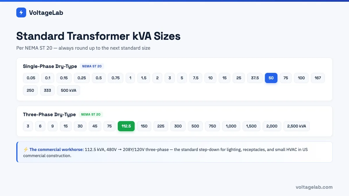
Transformers are manufactured in standard kVA sizes. Your calculated kVA is the minimum — always select the next standard size at or above your calculated value, never below. Running a transformer at or near 100% of its rated kVA continuously produces unnecessary heat and reduces service life.
Study smarter with VoltageLab
Built for electricians, apprentices, and electrical engineers who want faster practice and better exam prep.
Join thousands of electricians upgrading their skills
Standard Single-Phase Dry-Type Transformer Sizes
| Standard Single-Phase kVA Ratings | |||||
|---|---|---|---|---|---|
| 0.05 kVA | 0.1 kVA | 0.15 kVA | 0.25 kVA | 0.5 kVA | 0.75 kVA |
| 1 kVA | 1.5 kVA | 2 kVA | 3 kVA | 5 kVA | 7.5 kVA |
| 10 kVA | 15 kVA | 25 kVA | 37.5 kVA | 50 kVA | 75 kVA |
| 100 kVA | 167 kVA | 250 kVA | 333 kVA | 500 kVA | — |
Standard Three-Phase Dry-Type Transformer Sizes
| Standard Three-Phase kVA Ratings | |||||
|---|---|---|---|---|---|
| 3 kVA | 6 kVA | 9 kVA | 15 kVA | 30 kVA | 45 kVA |
| 75 kVA | 112.5 kVA | 150 kVA | 225 kVA | 300 kVA | 500 kVA |
| 750 kVA | 1,000 kVA | 1,500 kVA | 2,000 kVA | 2,500 kVA | — |
The most common commercial building transformer: The 112.5 kVA, 480V–208Y/120V three-phase unit is the standard workhorse of US commercial construction. It steps 480V service voltage down to the 208Y/120V used by most commercial loads (lighting, receptacles, small HVAC). If you work commercial construction and remember only one transformer size, know 112.5 kVA three-phase.
💡 Get step-by-step help with transformer calculations
VoltageLab’s AI Study Coach walks you through transformer sizing problems exactly as they appear on the NEC exam — kVA, FLC, and 450.3(B) OCPD sizing with explanations, not just answers.
kW to kVA — The Power Factor Relationship
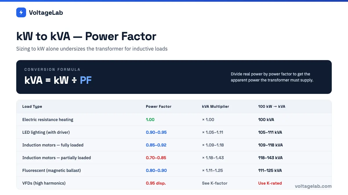
When a load specification gives you power in kW (real power) rather than kVA (apparent power), you must convert using the power factor before sizing the transformer.
kVA = kW ÷ Power Factor
Power factor ranges from 0 to 1.0. Pure resistive loads (electric heaters, incandescent lighting) have PF = 1.0, so kVA = kW. Inductive loads (motors, transformers, fluorescent lighting with magnetic ballasts, variable frequency drives) have PF less than 1.0 — meaning the transformer must supply more kVA than the kW figure alone suggests.
| Load Type | Typical Power Factor | kVA Multiplier vs kW | Example: 100 kW Load → Required kVA |
|---|---|---|---|
| Electric resistance heating | 1.00 | × 1.00 | 100 kVA |
| LED lighting (with driver) | 0.90–0.95 | × 1.05–1.11 | 105–111 kVA |
| Induction motors (fully loaded) | 0.85–0.92 | × 1.09–1.18 | 109–118 kVA |
| Induction motors (partially loaded) | 0.70–0.85 | × 1.18–1.43 | 118–143 kVA |
| Fluorescent lighting (magnetic ballast) | 0.80–0.90 | × 1.11–1.25 | 111–125 kVA |
| Variable frequency drives (VFDs) | 0.95 (displacement) but high harmonics — use K-factor transformer | See K-factor section | See K-factor section |
Example: A machine tool panel draws 85 kW at a power factor of 0.87. Required transformer kVA = 85 ÷ 0.87 = 97.7 kVA → select next standard size = 112.5 kVA three-phase.
How Much Sizing Margin to Add
The calculated kVA establishes the minimum. Selecting a transformer at exactly the minimum calculated kVA means it operates at 100% load continuously — which produces maximum heat, reduces insulation life, and leaves no headroom for load growth or load spikes from motor starting. Standard industry practice:
- 10–25% margin above calculated kVA for normal applications — the next standard size typically provides this margin automatically when you round up from the calculated value
- 125% of continuous load current — NEC requires that continuous loads (those running 3 hours or more) be calculated at 125% of their rated current. Apply this before sizing the transformer for circuits with continuous loads, then use that 125% value as your kVA basis
- Motor starting inrush: Induction motors draw 6–7× their full-load current at starting. While this lasts only seconds, it causes a voltage sag on the transformer secondary. For installations with large motors, the transformer kVA should account for the starting current impact on voltage regulation — typically requiring a transformer 20–30% larger than the motor’s running kVA demand alone
- Future growth: When the building program is known, size for the expected 5–10 year load, not just day-one load
K-Factor Transformers — When Standard Dry-Type Is Not Enough
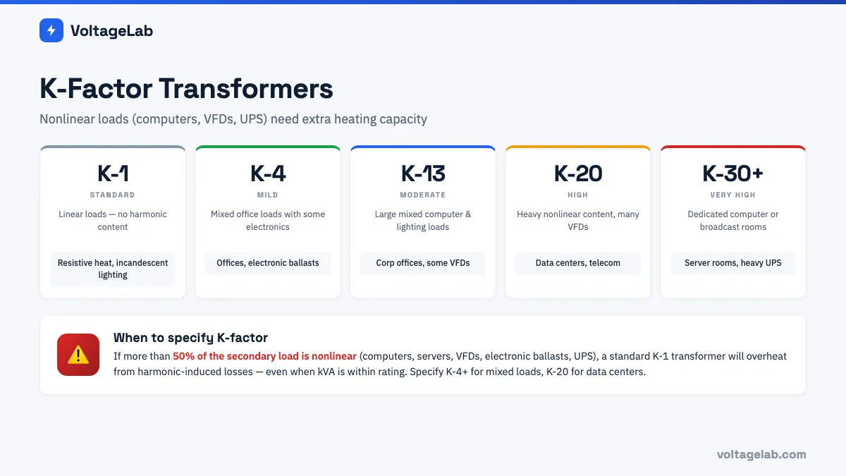
Standard dry-type transformers are designed for linear loads — loads that draw current in a sinusoidal waveform proportional to voltage. Nonlinear loads — including computers, servers, variable frequency drives, electronic ballasts, and uninterruptible power supplies — draw current in distorted, non-sinusoidal pulses that contain harmonic frequencies (3rd, 5th, 7th harmonics, etc.).
Harmonics cause additional heating in the transformer’s core and windings — particularly in the neutral conductor (where 3rd-order harmonics from single-phase nonlinear loads add rather than cancel) and in the eddy current losses in the core. A standard transformer running a data center or VFD-heavy load can overheat and fail prematurely, even when not overloaded in kVA terms.
K-factor is a measure of a load’s harmonic content and its impact on transformer heating. A K-factor rated transformer is designed and built to handle that additional heating without overtemperature.
| K-Factor Rating | Typical Load Profile | Common Applications |
|---|---|---|
| K-1 | Linear loads — no harmonic content | Resistive heating, incandescent lighting — standard transformer applies |
| K-4 | Mild harmonic content | Mixed office loads, fluorescent lighting with electronic ballasts, small number of computers |
| K-13 | Moderate to high harmonic content | Large office buildings with mixed computer and lighting loads, some VFDs |
| K-20 | High harmonic content | Data centers, telecommunications facilities, heavy VFD installations |
| K-30 / K-40 / K-50 | Very high harmonic content | Dedicated computer room panels, broadcast facilities, heavy UPS systems |
How to determine if a K-factor transformer is needed: If more than 50% of the load at the transformer secondary is nonlinear (computers, servers, VFDs, electronic ballasts, UPS systems), specify a K-4 or higher transformer. For facilities that are primarily data center or heavy VFD-driven process equipment, specify K-13 or K-20. NEMA ST 20 provides guidance on K-factor selection; an electrical engineer should specify the K-factor for large or complex installations.
Study smarter with VoltageLab
Built for electricians, apprentices, and electrical engineers who want faster practice and better exam prep.
⭐️ Join thousands of electricians upgrading their skills
Full-Load Current from kVA Rating
Once you have selected a transformer kVA, you need the full-load current (FLC) on both the primary and secondary to size conductors and OCPDs. Use the kVA-to-FLC formulas:
| kVA Rating | System | Primary 480V FLC | Secondary 208V FLC | Secondary 240V FLC (1-phase) | Secondary 120V FLC (1-phase) |
|---|---|---|---|---|---|
| 5 kVA | 1-phase | 10.4A | — | 20.8A | 41.7A |
| 10 kVA | 1-phase | 20.8A | — | 41.7A | 83.3A |
| 15 kVA | 1-phase | 31.3A | — | 62.5A | 125A |
| 25 kVA | 1-phase | 52.1A | — | 104.2A | 208.3A |
| 45 kVA | 3-phase | 54.1A | 124.9A | — | — |
| 75 kVA | 3-phase | 90.2A | 208.2A | — | — |
| 112.5 kVA | 3-phase | 135.3A | 312.4A | — | — |
| 150 kVA | 3-phase | 180.4A | 416.5A | — | — |
| 225 kVA | 3-phase | 270.6A | 624.7A | — | — |
| 300 kVA | 3-phase | 360.8A | 832.9A | — | — |
| 500 kVA | 3-phase | 601.4A | 1,388.2A | — | — |
Formula reminder: 1-phase: I = (kVA × 1,000) ÷ V | 3-phase: I = (kVA × 1,000) ÷ (1.732 × VL). Always verify against the actual transformer nameplate — nameplate FLC may differ slightly from calculated values due to transformer efficiency and impedance.
NEC 450.3(B) — OCPD Sizing for Transformers ≤1,000V
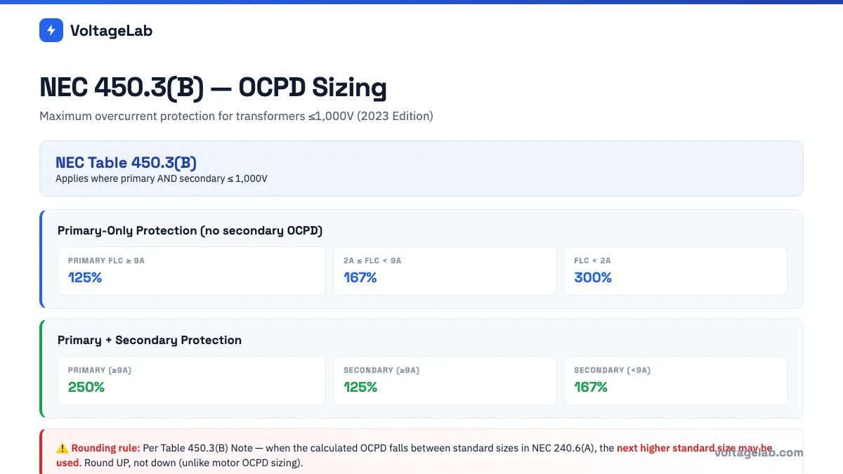
NEC Article 450.3(B) governs overcurrent protection for transformers with both primary and secondary voltage rated 1,000V or less. The rules define maximum OCPD percentages depending on whether you are providing primary-only protection or both primary and secondary protection.
Primary-Only Protection (No Secondary OCPD)
If you provide overcurrent protection only on the primary side, the primary OCPD must be sized at a maximum of 125% of primary FLC — provided the primary FLC is 9 amperes or more.
| Protection Scheme | Primary Current | Max Primary OCPD | Max Secondary OCPD |
|---|---|---|---|
| Primary Only (no secondary OCPD provided) | ≥9A | 125% of primary FLC | N/A |
| 2A to <9A | 167% of primary FLC | N/A | |
| <2A | 300% of primary FLC | N/A | |
| Primary + Secondary (both OCPDs provided) | ≥9A primary | 250% of primary FLC | 125% of secondary FLC |
| <9A primary | 250% of primary FLC | 167% of secondary FLC |
Rounding rule — NEC Table 450.3(B) Note: Where the calculated OCPD rating does not correspond to a standard OCPD size listed in NEC 240.6(A), the next higher standard size may be used. This is different from motor OCPD sizing, which requires rounding down in certain cases — for transformers, you round up when the calculation falls between standard sizes.
Which scheme to use:
- Primary-only (125%): Simpler installation, less equipment cost. Requires the transformer’s internal thermal protection (if listed) to serve as the secondary protection. Used on many commercial dry-type units with integral thermal cutouts.
- Primary + Secondary (250%/125%): Provides more complete protection — the secondary OCPD protects the secondary conductors from the transformer to the load panel more precisely. The primary OCPD at 250% is sized generously to allow the secondary OCPD to clear faults without the primary OCPD operating on inrush. Used where the secondary conductors run some distance to a panel and need their own protection.
Six Worked Sizing Examples
Example 1 — Small Single-Phase Control Transformer
Load: A 120V control panel draws 18A continuously. Primary: 480V single-phase from MCC.
- Secondary kVA = (V × I) ÷ 1,000 = (120 × 18) ÷ 1,000 = 2.16 kVA. Continuous load → multiply by 125%: 2.16 × 1.25 = 2.7 kVA minimum
- Next standard single-phase size: 3 kVA
- Primary FLC: (3 × 1,000) ÷ 480 = 6.25A
- NEC 450.3(B): Primary FLC 6.25A falls in “2A to <9A” row → primary-only OCPD max = 167% × 6.25 = 10.4A → next standard OCPD = 15A maximum
Example 2 — Standard 480V–208Y/120V Commercial Step-Down
Load: Office floor panel — load calculation = 85 kVA. Primary: 480V three-phase.
- Required kVA: 85 kVA (already in kVA)
- Add 25% margin: 85 × 1.25 = 106.25 kVA
- Next standard three-phase size: 112.5 kVA
- Primary FLC: (112.5 × 1,000) ÷ (1.732 × 480) = 135.3A
- Secondary FLC: (112.5 × 1,000) ÷ (1.732 × 208) = 312.4A
- NEC 450.3(B), Primary + Secondary: Primary OCPD max = 135.3 × 250% = 338.2A → 350A; Secondary OCPD max = 312.4 × 125% = 390.5A → 400A
Example 3 — 75 kVA Three-Phase, Primary-Only Protection
Transformer: 75 kVA, 480V–208Y/120V three-phase.
- Primary FLC: (75 × 1,000) ÷ (1.732 × 480) = 90.2A
- NEC 450.3(B), Primary-only: Primary FLC ≥9A → max primary OCPD = 90.2 × 125% = 112.75A → next standard = 125A maximum primary OCPD
Example 4 — kW Load with Power Factor
Load: Motor control center with 150 kW of motors at PF = 0.85.
- Convert kW to kVA: 150 ÷ 0.85 = 176.5 kVA
- Add 10% margin: 176.5 × 1.10 = 194.1 kVA
- Next standard three-phase size: 225 kVA
Example 5 — Data Center Panel (K-Factor Requirement)
Load: 200 kW of server and networking equipment (nonlinear loads) at estimated PF = 0.90.
- Convert: 200 ÷ 0.90 = 222.2 kVA
- Next standard size: 225 kVA — but this is 100% loaded with nonlinear loads
- Specify: 300 kVA K-20 rated transformer — provides 33% headroom, and K-20 handles harmonic heating
Example 6 — Finding Primary and Secondary FLC for Conductor Sizing
Transformer: 150 kVA, 480V primary → 208Y/120V secondary, three-phase.
- Primary FLC: (150 × 1,000) ÷ (1.732 × 480) = 180.4A
- Secondary FLC: (150 × 1,000) ÷ (1.732 × 208) = 416.5A
- Primary conductors: minimum ampacity = FLC per NEC 450.3(B) with the OCPD sizing
- Secondary conductors: minimum ampacity must match load requirements and secondary OCPD rating
Common Transformer Sizing Mistakes
Sizing to kW Instead of kVA
The most common error. A transformer is a kVA device — it must supply all apparent power, not just real power. For any load with a power factor less than 1.0 (motors, lighting with ballasts, VFDs), the required kVA is greater than the kW load. Divide kW by the power factor to get kVA before selecting a transformer size.
Not Applying 125% for Continuous Loads
Loads that operate continuously (3 hours or more) must be calculated at 125% per NEC 210.19(A)(1) and 215.2(A)(1). A transformer fed from these circuits must handle the 125% rated ampacity of those conductors.
Ignoring Motor Starting Inrush
Induction motors draw 6–7× full-load current at starting. This causes a voltage sag on the transformer secondary. For systems with large motors (typically 25 HP and above at low transformer kVA), verify that the voltage sag during motor starting does not cause problems for other sensitive loads on the same secondary. A transformer with lower impedance (2–3% vs the standard 5%) reduces voltage sag during motor starting.
Using a Standard Transformer for Heavy Nonlinear Loads
A data center, server room, or VFD-heavy machine room powered by a standard K-1 dry-type transformer will overheat from harmonic-induced losses even when the kVA load is within rating. Specify K-factor rated transformers for nonlinear load applications.
Rounding OCPD Down for Transformer Primary Protection
Unlike motor OCPD sizing, NEC Table 450.3(B) Note explicitly permits rounding up to the next standard OCPD size when the calculated value falls between standard sizes. Rounding down means the OCPD may trip during transformer energization inrush — causing nuisance outages.
Conclusion
Transformer sizing follows a consistent four-step process: calculate the required kVA (converting from kW if power factor is known), select the next standard kVA size above your calculated minimum, calculate primary and secondary FLC from that kVA and voltage, and size OCPDs per NEC Table 450.3(B).
Three rules to apply on every transformer selection:
- Always size in kVA, not kW. Divide kW by power factor to get kVA for any inductive or nonlinear load mix.
- For nonlinear loads (computers, VFDs, UPS), specify K-factor. A standard transformer on a data center load is an overheating problem waiting to happen.
- NEC 450.3(B) rounds up, not down. Use the next higher standard OCPD when the calculated value falls between standard sizes.
For full-load current formulas used in transformer sizing calculations, see our Essential Electrical Formulas: Ohm’s Law, Power & Voltage Drop. For the dwelling unit load calculations that drive transformer kVA selection in residential service work, see Electrical Load Calculator: NEC Article 220 Step-by-Step Guide.
📱 Master transformer sizing and every NEC calculation
VoltageLab gives you AI-generated practice questions on transformer kVA sizing, NEC 450.3(B) OCPD calculations, and every article on your journeyman or master exam — plus timed mock exams, flashcards, and an interactive circuit simulator. Free on iOS and Android.
Frequently Asked Questions
How do I calculate the kVA size of a transformer I need?
For single-phase: kVA = (V × I) ÷ 1,000, where V is the secondary voltage and I is the load current. For three-phase: kVA = (1.732 × VL × IL) ÷ 1,000, where VL is the line-to-line secondary voltage and IL is the line current. If your load is specified in kW rather than kVA, divide kW by the power factor first to get kVA. Always add a margin (typically next standard size above calculated) and apply 125% for continuous loads per NEC requirements.
What are the standard transformer kVA sizes?
Standard single-phase dry-type sizes include: 0.05, 0.1, 0.15, 0.25, 0.5, 0.75, 1, 1.5, 2, 3, 5, 7.5, 10, 15, 25, 37.5, 50, 75, 100, 167, 250, 333, and 500 kVA. Standard three-phase sizes include: 3, 6, 9, 15, 30, 45, 75, 112.5, 150, 225, 300, 500, 750, 1,000, 1,500, and 2,000 kVA. Always round up to the next standard size above your calculated requirement — never round down.
What does NEC 450.3(B) require for transformer OCPD sizing?
NEC 450.3(B) limits overcurrent protection for transformers with both primary and secondary voltages at 1,000V or less. With primary-only protection and primary FLC ≥9A, the maximum primary OCPD is 125% of primary FLC. With both primary and secondary OCPDs installed, the primary can be as large as 250% of primary FLC and the secondary at 125% of secondary FLC. Where the calculated OCPD does not correspond to a standard size, the next higher standard OCPD may be used per the table note.
When do I need a K-factor rated transformer?
A K-factor transformer is needed when the load contains significant nonlinear components — primarily computers, servers, variable frequency drives (VFDs), electronic ballasts, and UPS systems — that generate harmonic currents. These harmonics cause additional heating in standard transformer cores and windings beyond what the kVA rating alone accounts for. K-4 is appropriate for mixed office loads; K-13 for predominantly computer/VFD loads; K-20 or higher for data centers and heavy UPS installations. When more than 50% of the transformer secondary load is nonlinear, specify a K-factor rated transformer.
What is the most common commercial building transformer size?
The 112.5 kVA, 480V–208Y/120V three-phase dry-type transformer is the standard workhorse of US commercial construction. It steps 480V service or distribution voltage down to the 208Y/120V used by most commercial loads including lighting, receptacles, and small HVAC equipment. Its primary FLC is approximately 135A and secondary FLC approximately 312A at full rated kVA.
FREE PRACTICE TOOL
Think you'd pass this on a real exam?
Test what you just read with instant-feedback quizzes built around real code questions — not generic trivia.
5
Code standards
10,000+
Active learners
100%
Free to start
Instant explanations on every answer, right or wrong
NEC, BS7671, AS/NZS, CEC, and DIN VDE covered
Bite-sized quizzes you can finish in 5 minutes
No signup required to try your first quiz
No account needed · Takes less than 2 minutes