


Walk into any detached garage wired in the last twenty years and you will find the same box on the wall: a twelve-space load center fed by a 60 amp sub panel feeder off the house. It is the default answer when somebody wants power in a shop, a basement, an addition or a barn, and most of the time it is the right one.
The trouble starts when nobody checks the arithmetic. Sixty amps at 240 volts is 14,400 VA on paper and 48 amps of continuous load in practice, and that ceiling arrives faster than people expect once a welder, a mini-split and a car charger are all living in the same building. The wire size gets argued about on forums, the bonding screw gets left in, and the inspector writes it up.
Study smarter with VoltageLab
Built for electricians, apprentices, and electrical engineers who want faster practice and better exam prep.
⭐️ Join thousands of electricians upgrading their skills
This guide covers what a 60-amp sub-panel actually gives you, what wire size the NEC requires for each wiring method, how to size the feeder through Table 310.16 step by step, how to tell whether 60 amps is enough for your load, and the two mistakes that account for most failed sub-panel inspections.
Quick Answer
A 60 amp sub panel needs 6 AWG copper or 4 AWG aluminum ungrounded conductors, a full-size insulated neutral, and a 10 AWG copper equipment grounding conductor from Table 250.122. Both conductors carry 65 amps in the 75 °C column of NEC Table 310.16, which clears a 60-amp overcurrent device with room to spare.
Whether 60 amps is enough comes down to one number: 14,400 VA, of which only 48 amps may be continuous load under NEC 215.3. That covers a garage, a workshop, a finished basement or a small addition comfortably. It does not cover an electric range and an electric dryer in the same structure, whole-building resistance heat, or two EV chargers — run the Article 220 calculation before you buy the panel.
Key Takeaways
- 6 AWG copper and 4 AWG aluminum both carry 65 amps at 75 °C in NEC Table 310.16, which is the standard feeder for a 60-amp sub-panel
- 6 AWG aluminum carries only 50 amps at 75 °C and does not belong on a 60-amp feeder
- NM-B 6/3 cable is limited to the 60 °C column by NEC 334.80, so it is 55 amps and only works on a 60-amp breaker through the next-size-up rule in 240.4(B)
- Interior SER cable is not limited to 60 °C — NEC 338.10(B)(4)(a) specifically excludes 334.80, so 6 AWG copper SER is a full 65 amps
- The equipment grounding conductor for a 60-amp feeder is 10 AWG copper or 8 AWG aluminum per Table 250.122
- Every sub-panel runs four wires and keeps the neutral bar isolated from the ground bar — the main bonding jumper and the green bonding screw stay out, per NEC 408.40
- A sub-panel in a detached structure also needs its own grounding electrode system under 250.32(A) and a disconnecting means under 225.31
- 60 amps at 240 volts is 14,400 VA, and NEC 215.3 caps continuous load on that feeder at 48 amps
What a 60-amp sub-panel actually is
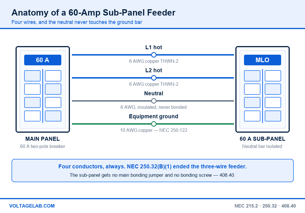
A sub-panel is a panelboard fed by a feeder instead of by service conductors. The 60-amp rating describes the overcurrent device protecting that feeder, not the panelboard itself. Four things make up the installation:
Pass your electrical exam the first time
Practice real NEC exam questions with full code-referenced explanations and progress tracking — built for journeyman, master and apprentice exam prep.
Thousands of NEC practice questions with code-referenced answers
- A two-pole 60-amp breaker in the upstream panel. This is the feeder overcurrent protection required by NEC 215.3, and it is what the panel downstream is named after.
- A four-wire feeder. Two ungrounded conductors, one insulated grounded conductor (neutral) and one equipment grounding conductor. NEC 250.32(B)(1) ended the old three-wire feeder to outbuildings in the 2008 Code.
- The panelboard. Usually a main-lug-only load center rated 100 or 125 amps. A panelboard may be rated higher than its feeder — NEC 408.36 only requires that the protecting device not exceed the panelboard rating.
- Separated bars. A neutral bar floating on insulated standoffs and a ground bar bonded to the enclosure, with nothing connecting the two.
What the 60-amp rating does and does not mean
Sixty amps is the most current the feeder is permitted to carry, and at 240 volts that works out to 14,400 volt-amperes. It is not a limit on how many breakers you can install. The 42-overcurrent-device ceiling came out of 408.36 in the 2008 NEC, so a 60-amp sub-panel can legally be full of twenty branch breakers as long as the calculated load stays inside the feeder.
What the rating does limit is continuous load. NEC 215.3 requires the feeder overcurrent device to be rated at not less than the noncontinuous load plus 125 percent of the continuous load. Turn that around and a 60-amp device supports 48 amps of continuous load — anything running three hours or more, which is most of what an EV charger, a heat pump or a shop dust collector does.
60-amp sub-panel wire size — copper, aluminum and cable types
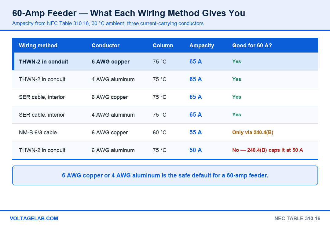
The wire size question has one answer for conduit and a different one for cable, because the wiring method decides which temperature column of NEC Table 310.16 you are allowed to read:
| Wiring method | Conductor | Column | Ampacity | 60 A feeder? |
|---|---|---|---|---|
| THWN-2 in conduit | 6 AWG copper | 75 °C | 65 A | Yes — the default |
| THWN-2 in conduit | 4 AWG aluminum | 75 °C | 65 A | Yes |
| SER cable, interior | 6 AWG copper / 4 AWG aluminum | 75 °C | 65 A | Yes |
| NM-B 6/3 cable | 6 AWG copper | 60 °C | 55 A | Only through 240.4(B) |
| THWN-2 in conduit | 6 AWG aluminum | 75 °C | 50 A | No |
Two rows deserve a second look. 6 AWG aluminum gets sold as “60-amp wire” and it is not — 50 amps at 75 °C means 240.4(B) lets you protect it at 60 amps only if the calculated load is 50 amps or less, and at that point you have a 50-amp sub-panel with a 60-amp label on it. Read up on why aluminum connections fail before you decide to save money there.
The other is SER. A lot of electricians still derate interior SER to the 60 °C column out of habit from the 2008 Code. The current text of 338.10(B)(4)(a) sends you to Part II of Article 334 excluding 334.80, so 6 AWG copper SER is a full 65 amps. The one exception is 10 AWG and smaller ungrounded conductors in contact with thermal insulation, which is not a 60-amp feeder’s problem.
The violation that fails the inspection: leaving the main bonding jumper or the green bonding screw installed in the sub-panel. NEC 408.40 requires the equipment grounding terminal bar to be bonded to the cabinet and the grounded conductor to stay off it. Bond them together and normal neutral current returns through the EGC, the conduit and anything else metallic in the path — energised metal, nuisance GFCI tripping, and a write-up every time.
Sizing the feeder — NEC 215.2, Table 310.16 and 110.14(C)
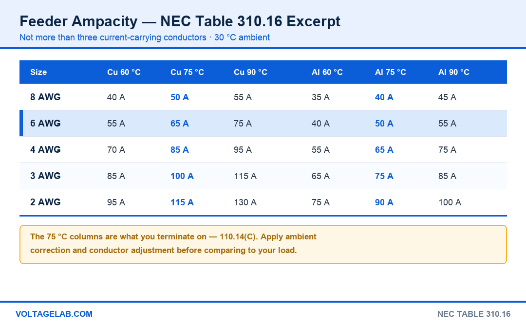
Every ampacity argument about sub-panels traces back to which column you are entitled to read. NEC 110.14(C)(1)(a) holds circuits rated 100 amps or less to the 60 °C column unless the equipment terminations are listed for higher. Modern load centers and breakers are marked 75 °C, so the 75 °C column is normally yours — but check the label on both ends before you rely on it.
| Size | Cu 60 °C | Cu 75 °C | Cu 90 °C | Al 60 °C | Al 75 °C | Al 90 °C |
|---|---|---|---|---|---|---|
| 8 AWG | 40 A | 50 A | 55 A | 35 A | 40 A | 45 A |
| 6 AWG | 55 A | 65 A | 75 A | 40 A | 50 A | 55 A |
| 4 AWG | 70 A | 85 A | 95 A | 55 A | 65 A | 75 A |
| 3 AWG | 85 A | 100 A | 115 A | 65 A | 75 A | 85 A |
| 2 AWG | 95 A | 115 A | 130 A | 75 A | 90 A | 100 A |
Six steps to size a 60-amp feeder correctly
- Calculate the load. Article 220, Part III for a new structure, or 220.87 for an existing one where you have twelve months of demand data. Add 125 percent of the continuous portion per 215.2(A)(1).
- Pick the overcurrent device. The next standard size from 240.6(A) at or above the calculated load — 60 amps for anything from 51 to 60 amps.
- Read the 75 °C column of Table 310.16 for your conductor material, after confirming both terminations are listed 75 °C.
- Correct for ambient using Table 310.15(B)(1) if the run passes through an attic or anywhere above 30 °C, then adjust under 310.15(C)(1) if more than three current-carrying conductors share the raceway. The neutral of a 120/240 V feeder is usually not counted.
- Compare the corrected ampacity to the load, not to the breaker. If it lands short, 240.4(B) permits the next standard device size up — but only when the conductor still carries the calculated load.
- Check voltage drop. Not enforceable, but the informational note to 215.2(A)(2) recommends holding feeders to 3 percent.
On that last point: using the dc resistance in Chapter 9, Table 8, a 6 AWG copper feeder pulling a full 60 amps at 240 volts hits 3 percent at roughly 120 feet one way. The same run in 4 AWG aluminum reaches it at about 75 feet. Detached-garage feeders cross those distances constantly, which is why so many of them end up in 4 AWG copper or 2 AWG aluminum. Our walkthrough of voltage drop calculations has the full method.
Sizing the neutral and the equipment ground
The equipment grounding conductor comes straight from Table 250.122 and it is sized on the overcurrent device, not on the load or the phase conductors: 10 AWG copper or 8 AWG aluminum for a 60-amp feeder. Upsize the ungrounded conductors for voltage drop and 250.122(B) makes you upsize the EGC proportionally. Our guide to equipment grounding conductors covers the proportional rule in detail.
The neutral is sized to the maximum unbalanced load under 220.61, which for a sub-panel feeding mostly 240-volt equipment can legitimately be smaller than the ungrounded conductors. Most electricians run it full size anyway — the cable assemblies come that way, and it removes an argument with the inspector. See neutral conductor sizing under 220.61 for the exceptions.
The one that catches everyone: 6/3 NM-B on a 60-amp breaker. NEC 334.80 pins NM cable to the 60 °C column no matter what the conductors are rated, so 6/3 NM is 55 amps — not 65. It is still legal on a 60-amp device through 240.4(B), but only if the calculated load is 55 amps or less. If your load calculation comes back at 58 amps, that cable is a violation and 4/3 NM or a conduit run is the fix.
Is a 60-amp sub-panel enough? Running the numbers
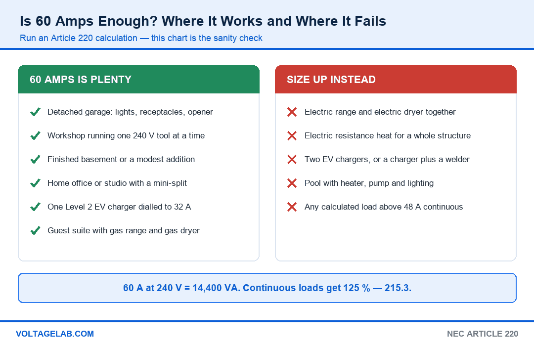
Sixty amps at 240 volts gives you 14,400 VA of connected capacity and 11,520 VA of continuous capacity. Against real equipment that is a generous budget for some buildings and nowhere near enough for others.
Study smarter with VoltageLab
Built for electricians, apprentices, and electrical engineers who want faster practice and better exam prep.
⭐️ Join thousands of electricians upgrading their skills
Where 60 amps is comfortably enough
- A detached garage with lighting, general receptacles and a door opener — rarely more than 20 amps of real demand
- A woodworking or metal shop where one 240-volt machine runs at a time: a 5 hp table saw draws roughly 24 amps at 240 V
- A finished basement or a modest addition with general lighting, receptacles and a mini-split
- A home office or studio, including a 240-volt ductless heat pump at 15 to 25 amps
- A single Level 2 EV charger dialled down to 32 amps, with light general load alongside it
- A guest suite where the range and dryer are gas
Where 60 amps runs out
- An electric range and an electric dryer in the same structure — 8,000 VA demand plus 5,000 VA gets you most of the way there before the lights go on
- Electric resistance heat for a whole building; even 10 kW is 41.7 amps at 240 V, all of it continuous
- Two EV chargers, or one charger plus a welder that anyone might strike while the car is plugged in
- A pool with a heater, a pump and lighting
- Any calculated load above 48 amps continuous, because 215.3 will not let you protect it at 60
A quick worked calculation
Take a 600 ft² detached shop. General lighting and receptacles at 3 VA/ft² is 1,800 VA. Two 20-amp small-appliance-style shop circuits add 3,000 VA. A 24-amp table saw at 240 V is 5,760 VA, and a 1.5-ton mini-split at 15 amps is 3,600 VA. That totals 14,160 VA, or 59 amps at 240 volts, before any demand factors — technically inside 60 amps and practically far too close to it. Apply the 125 percent continuous factor to the mini-split and you are over. This is exactly the point at which a 100-amp feeder costs a few hundred dollars more and removes the problem permanently. Our guide to calculating electrical load before adding a major appliance walks through the full Article 220 method.
60 amp vs 100 amp vs 125 amp sub-panel
| Consideration | 60 A sub-panel | 100 A sub-panel | 125 A sub-panel |
|---|---|---|---|
| Capacity at 240 V | 14,400 VA | 24,000 VA | 30,000 VA |
| Continuous limit (215.3) | 48 A | 80 A | 100 A |
| Copper conductor, 75 °C | 6 AWG | 3 AWG | 1 AWG |
| Aluminum conductor, 75 °C | 4 AWG | 1 AWG | 2/0 AWG |
| EGC, copper (250.122) | 10 AWG | 8 AWG | 6 AWG |
| Handles range + dryer | No | Yes | Yes |
| Handles a 48 A EV charger | No | Yes | Yes |
| Typical trench and conduit | 1 in. PVC | 1¼ in. PVC | 1½ in. PVC |
The difference in material cost between a 60-amp and a 100-amp feeder is usually a few hundred dollars. The difference in labour if you have to dig the trench twice is not. If the run is long, upsizing also solves the voltage drop problem for free. For the Code language behind all of this, see NEC Article 215 — Feeders, our breakdown of maximum load capacity rules for circuits, and NEC Article 250 grounding and bonding basics.
Is a 60-amp sub-panel the right choice?
Pros
- 6 AWG copper is the largest size most electricians can still terminate comfortably without a hydraulic crimper
- Fits a 1 in. PVC trench run, which is cheap to dig and easy to pull
- A 60-amp breaker usually drops into an existing main panel without a load calculation problem
- Enough capacity for a garage, shop, basement or addition that has no electric cooking or heating
- Panelboards rated 100 or 125 amps cost the same, so you keep the breaker spaces and the upgrade path
Cons
- 48 amps of continuous load disappears fast once an EV charger or heat pump is involved
- Voltage drop reaches 3 percent at about 120 feet in copper and 75 feet in aluminum
- Upsizing later means re-pulling the feeder, and often re-trenching
Installing a 60-amp sub-panel in the field
Do
- Remove the bonding screw or strap from the sub-panel and add a separate ground bar kit — 408.40
- Drive the grounding electrode system at a detached structure and land the GEC on the ground bar — 250.32(A)
- Install a disconnecting means at the detached structure, at the nearest point of entrance — 225.31 and 225.32
- Torque every lug to the value printed on the panel label, with a calibrated tool — 110.14(D)
- Keep 3 ft of working depth, 30 in. of width and 6½ ft of headroom in front of the panel — 110.26
Avoid
- Landing neutrals and grounds on the same bar because the panel came with only one
- Running a three-wire feeder to an outbuilding — that allowance died in the 2008 NEC
- Using 6 AWG aluminum and calling it a 60-amp feeder
- Mounting the panel in a bathroom or a clothes closet — 240.24(D) and 240.24(E)
- Skipping the load calculation because the last garage you wired worked out fine
Frequently asked questions
What size wire do I need for a 60 amp sub panel?
6 AWG copper or 4 AWG aluminum for the two ungrounded conductors, both of which carry 65 amps in the 75 °C column of NEC Table 310.16. Add an insulated neutral sized to the unbalanced load under 220.61 and a 10 AWG copper equipment grounding conductor from Table 250.122. If you are running NM-B cable, 6/3 is limited to 55 amps by 334.80 and only works when the calculated load stays at or below 55 amps.
Is a 60 amp sub panel enough for a garage?
For nearly every garage, yes. Lighting, general receptacles, a door opener and one 240-volt machine running at a time rarely exceed 35 amps of calculated demand. It stops being enough when the garage also has to feed an EV charger above 32 amps, electric heat, or a second large 240-volt tool that will run at the same time as the first.
Can I use 6/3 NM-B cable for a 60 amp sub panel?
Yes, conditionally. NEC 334.80 limits NM cable to the 60 °C column, so 6/3 NM-B is a 55-amp conductor. NEC 240.4(B) permits the next standard overcurrent device above the conductor ampacity, so a 60-amp breaker is legal — but only when the calculated load is 55 amps or less. If the calculation comes back higher, step up to 4/3 or move to conduit.
Do I need a ground rod for a 60 amp sub panel?
Only if the sub-panel is in a separate structure. NEC 250.32(A) requires a grounding electrode system at each building or structure supplied by a feeder, which in practice means two ground rods unless you can prove 25 ohms or less with one, or you have a concrete-encased electrode available. A sub-panel inside the same building as the service does not get its own electrode.
Why can’t the neutral and ground be bonded in a sub-panel?
Because bonding them creates a parallel path for normal neutral current. Downstream of the service disconnect, NEC 408.40 and 250.142(B) require the grounded conductor to stay separate from the equipment grounding conductor. Bond them at the sub-panel and return current splits between the neutral and every metallic path back to the main panel — conduit, ground wires, gas lines and water pipes included.
How many circuits can a 60 amp sub panel have?
As many as the panelboard has spaces for. The 42-circuit limit was removed from NEC 408.36 in the 2008 Code, so the only real constraint is the calculated load under Article 220. A twelve-space or twenty-space load center fed at 60 amps is entirely normal, because branch circuits are sized to their loads and almost never all draw at once.
Can a 60 amp breaker feed a 100 amp panel?
Yes. NEC 408.36 only requires that the overcurrent device protecting a panelboard not exceed the panelboard’s rating. A 100-amp or 125-amp main-lug-only load center protected by a 60-amp feeder breaker is code-compliant and common — it buys you breaker spaces now and an easy capacity upgrade later if you pull a larger feeder.
How far can I run a 60 amp sub panel feeder?
Ampacity does not change with distance, so there is no Code limit. Voltage drop is the practical one: at a full 60-amp load on 240 volts, 6 AWG copper reaches the recommended 3 percent at roughly 120 feet and 4 AWG aluminum at roughly 75 feet. Past that, upsize the ungrounded conductors and upsize the equipment grounding conductor proportionally under 250.122(B).
The bottom line
A 60-amp sub-panel earns its place because 6 AWG copper is the last size an electrician can terminate with hand tools, it fits a 1-inch trench, and it covers the load of almost any garage, shop, basement or addition that does not cook or heat with electricity. Wire it with 6 AWG copper or 4 AWG aluminum, a full-size insulated neutral and a 10 AWG copper EGC, and it will pass inspection anywhere in the country.
Two restraints decide whether it is the right call. The first is 48 amps of continuous load under 215.3 — one Level 2 charger or one heat pump eats most of that, so run the Article 220 numbers before you commit. The second is distance, because voltage drop, not ampacity, is what makes long feeders fail in service. Get both right and the only thing left is the bonding screw: pull it out, keep the bars separated, and check your sizing against the NEC 310.16 ampacity chart before the wire goes in the trench.
FREE PRACTICE TOOL
Think you'd pass this on a real exam?
Test what you just read with instant-feedback quizzes built around real code questions — not generic trivia.
5
Code standards
10,000+
Active learners
100%
Free to start
Instant explanations on every answer, right or wrong
NEC, BS7671, AS/NZS, CEC, and DIN VDE covered
Bite-sized quizzes you can finish in 5 minutes
No signup required to try your first quiz
No account needed · Takes less than 2 minutes