


Stand at the wire cage of any supply house on a Saturday and somebody will be holding a 100-amp breaker, asking which reel goes with it. Often they leave with 2-2-2-4 aluminum SER because the shelf tag says “100 amp” — and that cable ends up on a breaker it was never allowed to sit on.
The 100 amp sub panel wire size question trips people up because there are three different answers floating around and only one of them applies to a sub-panel. Service conductors get an 83% allowance. Cable gets held to a lower temperature column. And the next-size-up rule in 240.4(B) works for some conductor sizes but not others. Mix those up and the feeder is either undersized or written up.
Study smarter with VoltageLab
Built for electricians, apprentices, and electrical engineers who want faster practice and better exam prep.
⭐️ Join thousands of electricians upgrading their skills
This guide covers the four conductors in a 100-amp sub-panel feeder, the wire size for each wiring method, the step-by-step sizing through NEC 215.2, Table 310.16 and 110.14(C), when distance forces you to upsize, and the mistakes behind most failed sub-panel inspections.
Quick Answer
A 100 amp sub panel needs 3 AWG copper or 1 AWG aluminum ungrounded conductors, sized from the 75 °C column of NEC Table 310.16, plus a full-size insulated neutral and an equipment grounding conductor of 8 AWG copper or 6 AWG aluminum from Table 250.122. That is four wires, every time.
The 4 AWG copper / 2 AWG aluminum sizes you see on 100-amp services come from the 83% rule in NEC 310.12, which does not apply to a sub-panel feeder. If the breaker or panel lugs are only rated 60 °C, step up to 1 AWG copper or 1/0 AWG aluminum. On runs longer than about 180 feet, upsize for voltage drop and increase the ground with it.
Key Takeaways
- 3 AWG copper and 1 AWG aluminum both carry exactly 100 amps in the 75 °C column of NEC Table 310.16
- The 83% sizing in NEC 310.12 applies only to services and feeders carrying the entire load of a one-family dwelling, never to a sub-panel
- 2-2-2-4 aluminum SER is a 90-amp cable, and 240.4(B) cannot round it up to 100 amps because 90 amps is a standard breaker size
- The equipment grounding conductor for a 100-amp feeder is 8 AWG copper or 6 AWG aluminum per NEC Table 250.122
- Upsizing the ungrounded conductors for voltage drop requires a proportional increase in the equipment grounding conductor under NEC 250.122(B)
- A sub-panel keeps the neutral bar isolated from the ground bar, with the bonding screw removed, per NEC 408.40 and 250.24(A)(5)
- A 100-amp feeder delivers 24,000 VA at 240 volts, of which 80 amps may be continuous load under NEC 215.3
What makes up a 100-amp sub-panel feeder
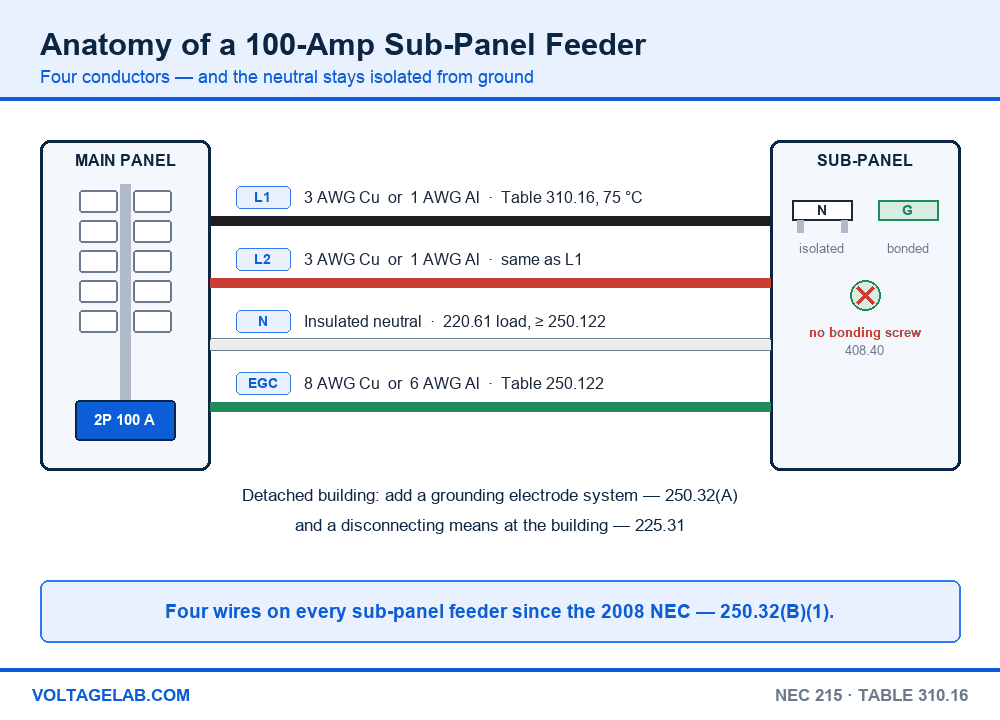
A sub-panel is a panelboard supplied by a feeder rather than by service conductors. The “100 amp” in the name describes the overcurrent device protecting that feeder in the upstream panel. The panelboard itself is often rated 125 or 200 amps, which is fine — NEC 408.36 only requires that the protective device not exceed the panelboard rating.
Pass your electrical exam the first time
Practice real NEC exam questions with full code-referenced explanations and progress tracking — built for journeyman, master and apprentice exam prep.
Thousands of NEC practice questions with code-referenced answers
“What size wire for a 100 amp sub panel” is really four questions, because four conductors run between the panels and each one is sized by a different rule:
- Two ungrounded conductors. The hots. 3 AWG copper or 1 AWG aluminum, from the 75 °C column of Table 310.16, assuming 75 °C terminations at both ends.
- One grounded conductor. The neutral. Sized to the calculated unbalanced load under NEC 220.61, and never smaller than Table 250.122 requires (NEC 215.2(A)(2)). In practice it is full size.
- One equipment grounding conductor. 8 AWG copper or 6 AWG aluminum from Table 250.122, based on the 100-amp feeder breaker. Metal raceway may serve as the EGC under 250.118, but pull a wire anyway.
- A grounding electrode conductor — only if the sub-panel is in a detached building, where 250.32(A) requires its own electrode system. Size it from Table 250.66; for 3 AWG copper feeders that is 8 AWG copper, or 6 AWG where it runs only to ground rods.
The three-wire feeder to an outbuilding ended with 250.32(B)(1) in the 2008 NEC. Our guide to grounding an electrical panel covers the bonding side in detail.
Reading SER cable markings like 2-2-2-4 and 1-1-1-3
SER cable is sold by four numbers, and they read in order: hot – hot – neutral – ground. 1-1-1-3 aluminum SER is two 1 AWG ungrounded conductors, a 1 AWG insulated neutral and a 3 AWG bare ground. 2-2-2-4 is the same layout one size smaller. The first number decides the breaker — and a 2 there means 90 amps in aluminum.
100-amp sub-panel wire size by material and wiring method — NEC Table 310.16
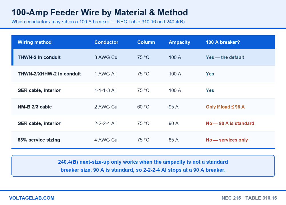
Material and wiring method decide which column of Table 310.16 you may read:
| Wiring method | Conductor | Column | Ampacity | On a 100 A breaker? |
|---|---|---|---|---|
| THWN-2 in conduit | 3 AWG copper | 75 °C | 100 A | Yes — the default |
| THWN-2 / XHHW-2 in conduit | 1 AWG aluminum | 75 °C | 100 A | Yes |
| SER cable, interior | 1-1-1-3 aluminum | 75 °C | 100 A | Yes |
| NM-B 2/3 cable | 2 AWG copper | 60 °C | 95 A | Only if calculated load ≤ 95 A |
| SER cable, interior | 2-2-2-4 aluminum | 75 °C | 90 A | No — 90 A breaker |
| Any method, 83% sizing | 4 AWG Cu / 2 AWG Al | 75 °C | 85 A / 90 A | No — services only |
The NM-B and SER rows are where the arguments start. NM-B is held to the 60 °C column by NEC 334.80, and the cable tops out at 2 AWG copper, which is 95 amps. Since 95 is not a standard breaker size, 240.4(B) lets you protect it at 100 amps — but only if the calculated load is 95 amps or less. Interior SER is different: 338.10(B)(4)(a) sends you to Part II of Article 334 excluding 334.80, so SER reads the 75 °C column.
That is exactly why 2-2-2-4 aluminum fails. At 75 °C, 2 AWG aluminum is 90 amps. The next-size-up rule only applies when the conductor ampacity does not match a standard rating in 240.6(A), and 90 amps is a standard rating. So the cable stops at a 90-amp breaker. If you want 100 amps out of SER, buy 1-1-1-3.
The 83% trap: 4 AWG copper and 2 AWG aluminum are legal on a 100-amp service because NEC 310.12 lets dwelling service conductors, and feeders carrying the entire load of a one-family dwelling, be sized at 83% of the rating. A sub-panel feeding a garage, a basement or an addition carries only part of the load, so it gets no 83% allowance. 4 AWG copper on a 100-amp sub-panel breaker is an 85-amp conductor on a 100-amp device — and it is one of the most common write-ups on residential sub-panels.
If you are wiring the service itself, the 83% numbers do apply — our guide to what size wire for a 100-amp service walks through Table 310.12(A) and the conditions that come with it.
Sizing the feeder — NEC 215.2, Table 310.16 and 110.14(C)
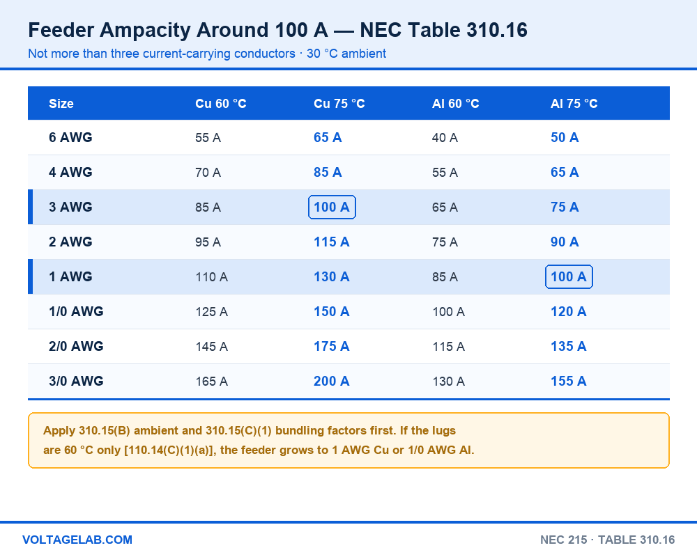
Feeder conductors are sized under NEC 215.2(A)(1) from Table 310.16, which assumes not more than three current-carrying conductors in a raceway or cable and a 30 °C (86 °F) ambient. These are the sizes on either side of a 100-amp decision. Our walkthrough of how to read NEC Table 310.16 covers the table itself in more depth.
| Size | Copper 60 °C | Copper 75 °C | Aluminum 60 °C | Aluminum 75 °C |
|---|---|---|---|---|
| 6 AWG | 55 A | 65 A | 40 A | 50 A |
| 4 AWG | 70 A | 85 A | 55 A | 65 A |
| 3 AWG | 85 A | 100 A | 65 A | 75 A |
| 2 AWG | 95 A | 115 A | 75 A | 90 A |
| 1 AWG | 110 A | 130 A | 85 A | 100 A |
| 1/0 AWG | 125 A | 150 A | 100 A | 120 A |
| 2/0 AWG | 145 A | 175 A | 115 A | 135 A |
| 3/0 AWG | 165 A | 200 A | 130 A | 155 A |
Step-by-step: sizing a 100-amp sub-panel feeder
Step 1 — calculate the load. Run the Article 220 calculation for everything the sub-panel will serve. Under 215.2(A)(1)(a) the conductor ampacity must be at least the noncontinuous load plus 125% of the continuous load. Anything running three hours or more is continuous.
Step 2 — pick the breaker. NEC 215.3 applies the same 125% test to the overcurrent device. A 100-amp breaker therefore supports 80 amps of continuous load.
Step 3 — check the terminations. NEC 110.14(C)(1)(a) holds circuits rated 100 amps or less, and conductors 14 through 1 AWG, to the 60 °C column unless the equipment is listed and marked for 75 °C. Nearly every modern breaker and load center is marked 60/75 °C, which puts you in the 75 °C column: 3 AWG copper or 1 AWG aluminum. On an older panel marked 60 °C only, the answer becomes 1 AWG copper (110 A) or 1/0 aluminum (100 A).
Study smarter with VoltageLab
Built for electricians, apprentices, and electrical engineers who want faster practice and better exam prep.
⭐️ Join thousands of electricians upgrading their skills
Step 4 — correct and adjust. Start from the 90 °C value of THWN-2 or XHHW-2 and apply the 310.15(B) ambient correction for a hot attic or a rooftop run, then the 310.15(C)(1) adjustment if more than three current-carrying conductors share the raceway. The neutral of a 120/240-volt feeder does not count, per 310.15(E)(1). The result still cannot exceed the 75 °C ampacity.
Step 5 — size the neutral and the ground. Neutral from the 220.61 unbalanced load, not smaller than Table 250.122. EGC from Table 250.122: 8 AWG copper or 6 AWG aluminum for a 100-amp device. See NEC 250.122 explained for the full table.
Step 6 — check the distance. Voltage drop is not a mandatory rule for most feeders, but the informational notes in 215.2(A) recommend no more than 3% on the feeder and 5% overall. Past roughly 180 feet at a realistic load, 3 AWG copper exceeds that — see the voltage drop table below.
The one that catches everyone: when you upsize the hots for voltage drop, NEC 250.122(B) requires the equipment grounding conductor to grow by the same circular-mil ratio. Bump a 100-amp feeder from 3 AWG copper (52,620 cmil) to 2 AWG (66,360 cmil) and the ratio is 1.26 — the 8 AWG EGC (16,510 cmil) becomes 20,821 cmil, which means 6 AWG copper. Pulling bigger hots with the original 8 AWG ground is a violation even though the ground matches Table 250.122.
What passes inspection — and what does not
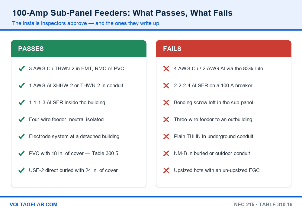
Permitted
- 3 AWG copper THWN-2 in EMT, RMC, IMC or PVC — the default conduit feeder
- 1 AWG aluminum XHHW-2 or THWN-2 in conduit, with terminations listed for aluminum
- 1-1-1-3 aluminum SER run inside the building, read at the 75 °C column per 338.10(B)(4)(a)
- NM-B 2/3 in a dwelling where the calculated load is 95 amps or less, under 240.4(B)
- PVC with at least 18 inches of cover, or USE-2 / listed direct-burial cable with 24 inches of cover, per Table 300.5
- A main-breaker panel or other disconnect at a detached building, as required by 225.31, plus its own grounding electrode system under 250.32(A)
Not permitted
- 4 AWG copper or 2 AWG aluminum on a 100-amp sub-panel breaker using the 310.12 service allowance
- 2-2-2-4 aluminum SER on a 100-amp breaker
- The main bonding jumper or green bonding screw left installed in the sub-panel — 408.40 and 250.24(A)(5)
- A three-wire feeder (no EGC) to a detached building — 250.32(B)(1)
- Plain THHN in underground conduit, which 300.5(B) treats as a wet location — use THWN-2 or XHHW-2
- NM-B in buried conduit or any wet or damp location — 334.12(B)
Voltage drop on long 100-amp feeders
Detached shops and barns are where these feeders get long. The table gives the maximum one-way distance for 3% drop at 240 volts and 80 amps, the continuous limit of a 100-amp breaker.
| Conductor | Area (cmil) | Max one-way length at 3% | EGC if upsized from base size |
|---|---|---|---|
| 3 AWG copper | 52,620 | about 183 ft | 8 AWG Cu (base size) |
| 2 AWG copper | 66,360 | about 231 ft | 6 AWG Cu |
| 1 AWG copper | 83,690 | about 292 ft | 4 AWG Cu (26,258 cmil needed) |
| 1 AWG aluminum | 83,690 | about 177 ft | 6 AWG Al (base size) |
| 1/0 AWG aluminum | 105,600 | about 224 ft | 4 AWG Al (33,110 cmil needed) |
| 2/0 AWG aluminum | 133,100 | about 282 ft | 4 AWG Al (41,732 cmil needed) |
For a 150-foot run of 3 AWG copper at 80 amps the drop works out to 5.9 volts, or 2.5% — inside the recommendation. Our guide to voltage drop calculations covers the formula and the three-phase version. If you go to conduit, three 3 AWG THHN plus an 8 AWG EGC total 0.3285 in², just inside the 40% fill of 1-inch EMT; most electricians step up to 1-1/4 inch for an easier pull.
100-amp sub-panel vs 60, 125 and 200 amps
All values assume 75 °C terminations and no correction or adjustment:
| Feeder breaker | Copper | Aluminum | EGC (Table 250.122) | Capacity at 240 V | Max continuous |
|---|---|---|---|---|---|
| 60 A | 6 AWG | 4 AWG | 10 Cu / 8 Al | 14,400 VA | 48 A |
| 100 A | 3 AWG | 1 AWG | 8 Cu / 6 Al | 24,000 VA | 80 A |
| 125 A | 1 AWG | 2/0 AWG | 6 Cu / 4 Al | 30,000 VA | 100 A |
| 200 A | 3/0 AWG | 250 kcmil | 6 Cu / 4 Al | 48,000 VA | 160 A |
Notice the jump between 100 and 125 amps: two copper sizes and three aluminum sizes for 25 more amps. That is why 100 amps is the sweet spot for most garages and shops. If the load calculation comes in well under 48 amps continuous, the 60-amp sub-panel costs less to wire. For the Article 215 rules behind all of these rows, see our summary of Article 215 feeders, and if you are choosing aluminum, read why aluminum connections fail before you torque the lugs.
Is a 100-amp sub-panel the right choice?
Pros
- 24,000 VA covers a shop with a welder, a mini-split and a Level 2 EV charger
- 3 AWG copper and 1 AWG aluminum are stock sizes at every supply house
- 1-1-1-3 aluminum SER keeps interior runs cheap and fast to install
- Leaves headroom over a 60-amp feeder without the conductor cost of 125 amps
Cons
- May exceed the spare capacity of a 100-amp or 150-amp service — run the 220 calculation on the house first
- Long runs to detached buildings push you into upsized conductors and a bigger EGC
- Two EV chargers or whole-building electric heat can outgrow it
Wiring a 100-amp sub-panel in the field
Do
- Read the temperature marking on the breaker and panel lugs before you pick a column
- Remove the bonding screw or strap and land the neutral on the isolated bar
- Torque every lug to the marked value with a calibrated tool, per 110.14(D)
- Use antioxidant compound on aluminum where the lug manufacturer calls for it
- Drive the electrode system at a detached building and bond it to the ground bar
Avoid
- Using Table 310.12(A) service sizes for a sub-panel feeder
- Buying 2-2-2-4 SER because the shelf tag says “100 amp”
- Upsizing the hots for distance and forgetting the EGC
- Pulling plain THHN or NM-B into underground conduit
- Bonding neutral and ground together in the sub-panel
Frequently asked questions
What size wire do I need for a 100 amp sub panel?
3 AWG copper or 1 AWG aluminum for the two hots, a full-size insulated neutral, and an 8 AWG copper or 6 AWG aluminum equipment grounding conductor. That assumes 75 °C terminations and a run under about 180 feet.
Can I use 4 AWG copper for a 100 amp sub panel?
No. 4 AWG copper is 85 amps at 75 °C. It is legal on a 100-amp dwelling service only because NEC 310.12 permits 83% sizing there, and that allowance does not extend to a feeder that carries only part of the dwelling load. The largest breaker 4 AWG copper can take on a sub-panel is 90 amps, under 240.4(B).
Is 2-2-2-4 aluminum SER good for 100 amps?
Not on a sub-panel feeder. 2 AWG aluminum is 90 amps at 75 °C, and because 90 amps is a standard breaker size the next-size-up rule does not apply. Use a 90-amp breaker, or buy 1-1-1-3 aluminum SER for a full 100 amps.
What size ground wire for a 100 amp sub panel?
8 AWG copper or 6 AWG aluminum per NEC Table 250.122, based on the 100-amp feeder breaker. If you upsize the ungrounded conductors for voltage drop, 250.122(B) requires the ground to increase in proportion.
Can I run Romex to a 100 amp sub panel?
Only inside a dwelling and only in the largest size. NM-B tops out at 2 AWG copper, which is 95 amps at the 60 °C column required by 334.80. It can sit on a 100-amp breaker under 240.4(B) if the calculated load is 95 amps or less. NM-B is never permitted in underground conduit or other wet locations.
How far can I run 3 AWG copper to a 100 amp sub panel?
About 180 feet one way keeps voltage drop at 3% with an 80-amp load on 240 volts. Beyond that, step up to 2 AWG or 1 AWG copper and increase the equipment grounding conductor under 250.122(B).
The bottom line
A 100-amp sub-panel is the right size for most garages, shops and additions, and the wire is simple once you separate it from the service rules: 3 AWG copper or 1 AWG aluminum, a full-size neutral, and an 8 AWG copper or 6 AWG aluminum ground. The two restraints that keep it legal are not borrowing the 83% sizing from 310.12, and not letting 240.4(B) talk you into 90-amp conductors on a 100-amp breaker.
Check the lug temperature rating, keep neutral and ground apart, and upsize the ground with the hots on a long run. For the conductor itself, our guide to THHN/THWN-2 wire covers which marking you need for underground and outdoor feeders.
FREE PRACTICE TOOL
Think you'd pass this on a real exam?
Test what you just read with instant-feedback quizzes built around real code questions — not generic trivia.
5
Code standards
10,000+
Active learners
100%
Free to start
Instant explanations on every answer, right or wrong
NEC, BS7671, AS/NZS, CEC, and DIN VDE covered
Bite-sized quizzes you can finish in 5 minutes
No signup required to try your first quiz
No account needed · Takes less than 2 minutes