


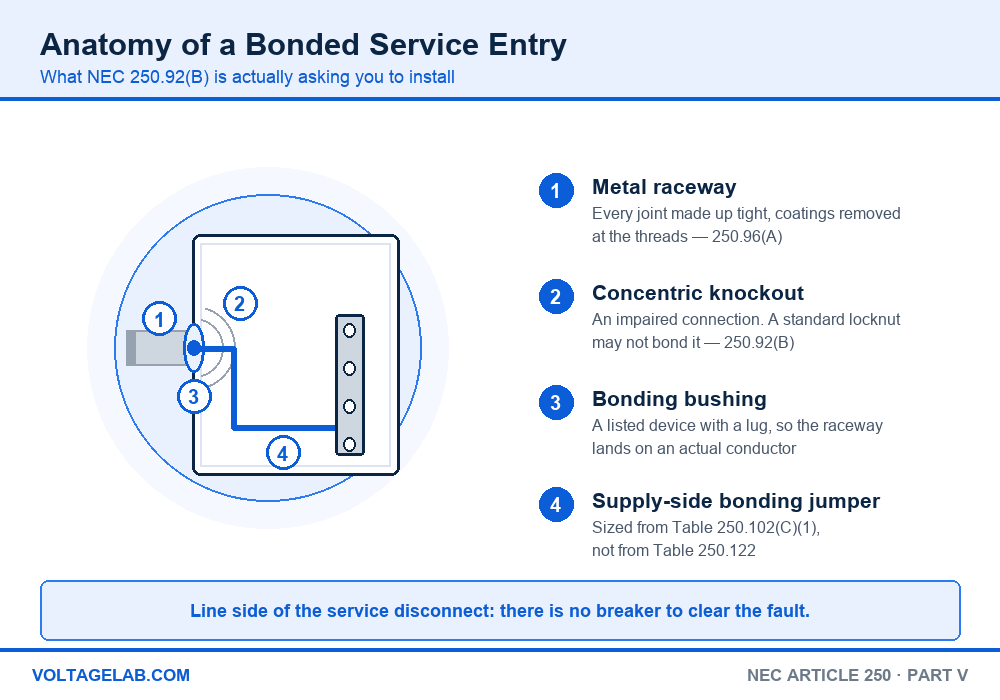
Pull the cover off a 400-amp meter main and look at where the service raceway lands. Nine times out of ten there is a locknut inside, a locknut outside, and a set of concentric rings still sitting in the sheet metal around the hole. The conduit is mechanically solid. Electrically, on the line side of the disconnect, it is not bonded — and that is a violation of NEC 250.92(B).
This catches experienced electricians because the same detail is perfectly legal six inches downstream. Part V of Article 250 splits at the service disconnect: everything on the line side gets one set of rules and one sizing table, and everything on the load side gets a different set and a different table. Use the wrong one and the jumper is either undersized or missing entirely.
Study smarter with VoltageLab
Built for electricians, apprentices, and electrical engineers who want faster practice and better exam prep.
⭐️ Join thousands of electricians upgrading their skills
This guide walks NEC 250.90 through 250.102 section by section — what each one requires, which of the four bonding jumpers you are sizing, which table to open, and the specific details that fail inspections.
Quick Answer
NEC 250.90 through 250.102 is Part V of Article 250, and it covers bonding — the requirement that every metal part likely to carry fault current be connected together well enough to carry it. 250.90 sets the performance rule, 250.92 through 250.100 say where the connection must be more than a locknut, and 250.102 sizes and installs the jumper.
The one thing to carry onto the job: line-side jumpers size from Table 250.102(C)(1) based on the ungrounded supply conductors, and load-side jumpers size from Table 250.122 based on the overcurrent device. There is no breaker upstream of the service disconnect to clear a fault, which is why the line side gets the stricter treatment.
Key Takeaways
- NEC 250.90 is a performance rule — bonding must be able to carry the fault current likely to be imposed, not merely make contact
- Standard locknuts and bushings may make the mechanical connection at a service, but they cannot be the only means of bonding under 250.92(B)
- Concentric knockouts, eccentric knockouts, oversized knockouts and reducing washers are all treated as impaired connections that must be bonded around
- Supply-side, main and system bonding jumpers all size from Table 250.102(C)(1) using the ungrounded supply conductors
- Equipment bonding jumpers on the load side size from Table 250.122 using the overcurrent device rating
- NEC 250.97 extends the service-grade bonding methods to any circuit over 250 volts to ground, so 277/480 V systems get the same treatment at ringed knockouts
- A bonding jumper run outside the raceway is limited to 6 feet and must follow the raceway, per 250.102(E)(2)
What NEC 250.90 actually requires
Section 250.90 is two lines long and it is the reason every other section in Part V exists: bonding shall be provided where necessary to ensure electrical continuity and the capacity to conduct safely any fault current likely to be imposed on it.
Pass your electrical exam the first time
Practice real NEC exam questions with full code-referenced explanations and progress tracking — built for journeyman, master and apprentice exam prep.
Thousands of NEC practice questions with code-referenced answers
Read the second half of that sentence carefully. It is a performance requirement, not a connection requirement. Two pieces of metal touching are electrically continuous. They are not necessarily capable of carrying 20,000 amps for the few cycles it takes an upstream device to open. Everything from 250.92 to 250.102 is the Code spelling out where ordinary hardware fails that test and what to install instead. If you want the wider context first, our overview of NEC Article 250 grounding and bonding maps all ten parts of the article.
Line side and load side — what the words mean here
Everything in Part V hinges on which side of the service disconnecting means you are standing on.
- Line side. Upstream of the service disconnect — the service raceway, the meter enclosure, the wireway, the disconnect enclosure itself. There is no overcurrent device between this metal and the utility transformer. A ground fault here is cleared by the utility’s primary protection, or by the conductor burning open.
- Load side. Downstream of the service disconnect, and downstream of any separately derived system. A ground fault here is cleared by a breaker or fuse whose rating you know, which is why the load-side jumper can be sized from that rating.
That asymmetry explains the whole part. On the load side the Code knows the maximum current the fault path will see. On the line side it does not, so it sizes the bonding path off the supply conductors instead — the only thing that limits the fault.
The four bonding jumpers and where each one lives
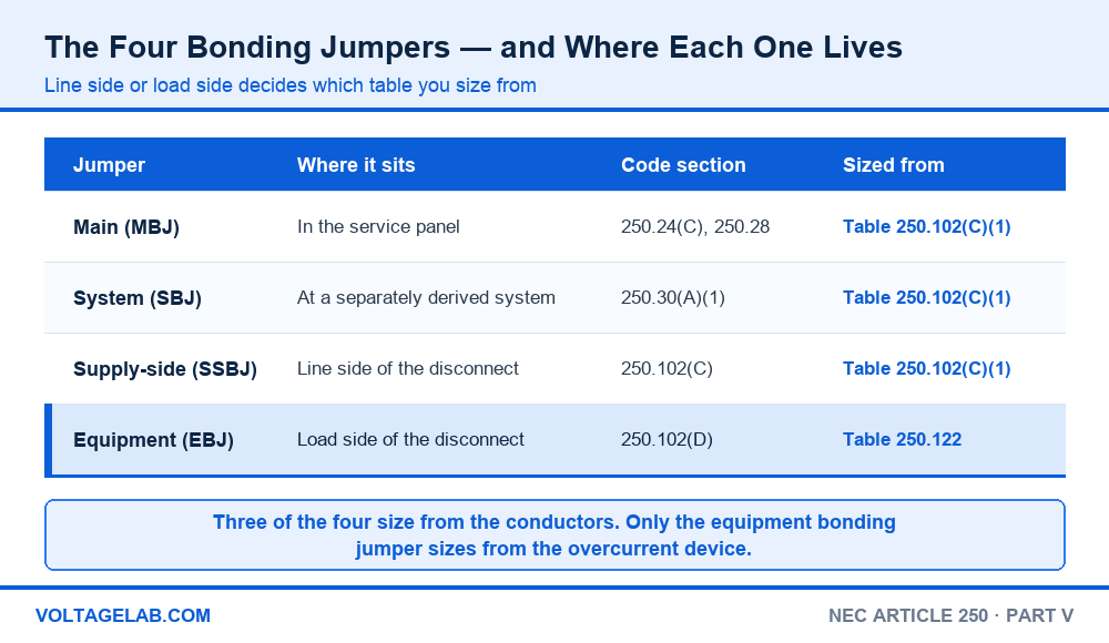
Article 250 defines four separate jumpers. They are not interchangeable names for the same conductor, and three of the four share a sizing table:
| Jumper | Where it sits | Code section | Sized from |
|---|---|---|---|
| Main bonding jumper | Inside the service disconnect enclosure | 250.24(C), 250.28 | Table 250.102(C)(1) |
| System bonding jumper | At a separately derived system | 250.30(A)(1) | Table 250.102(C)(1) |
| Supply-side bonding jumper | Line side of the service disconnect | 250.102(C) | Table 250.102(C)(1) |
| Equipment bonding jumper | Load side of the disconnect | 250.102(D) | Table 250.122 |
The equipment bonding jumper is the odd one out, and it is the one people reach for by habit. If you are bonding a raceway on the line side of the service disconnect and you sized the jumper off the breaker, you sized it from the wrong table. Our dedicated guide to bonding jumper types and sizing works through each one with numbers.
NEC 250.92 — bonding at the service
250.92(A) lists what must be bonded: service raceways, cable trays, cablebus frameworks, auxiliary gutters, service equipment enclosures, metering enclosures, and any enclosure or raceway containing a grounding electrode conductor. If service conductors pass through it and it is metal, it is on the list.
250.92(B) is the part that gets cited on correction notices. Electrical continuity at those enclosures must be ensured by one of four methods:
- Bonding the equipment to the grounded service conductor in a manner provided in 250.8
- Connections using threaded couplings or threaded hubs on enclosures, made up wrenchtight
- Threadless couplings and connectors made up tight, for metal raceways and metal-clad cables
- Other listed devices — bonding-type locknuts, bonding bushings, or bushings with bonding jumpers
And then the sentence that decides most inspections: bonding jumpers meeting the requirements of Article 250 shall be used around impaired connections, such as reducing washers or oversized, concentric or eccentric knockouts. Standard locknuts or bushings are permitted to make the mechanical connection, but they shall not be the only means of bonding.
The concentric knockout trap: a double-locknut connection into a service enclosure is a legitimate bonding method — but only if the sheet metal around the hole is solid. The moment there are concentric or eccentric rings left in place, the current has to cross a punched, partially-sheared ring to reach the enclosure, and 250.92(B) calls that an impaired connection. Either knock every ring out so the locknut bears on solid metal, or install a bonding bushing and a jumper. This is one of the most-cited service violations in the Code.
The same logic covers reducing washers. A 2-inch knockout filled with a reducing washer to take a 1-inch connector has two extra sheet-metal interfaces in the fault path, and the Code does not accept them on the line side. Bond around it. If you are choosing hardware for this, our comparison of grounding bushings versus bonding bushings covers what the listing on each one actually buys you.
NEC 250.94 through 250.100 — the four sections people skip
Between the service rules and the sizing rules sit four short sections. None of them is long, and each one covers a situation that is easy to miss on a walkthrough.
250.94 — intersystem bonding termination
Every service needs an accessible means for the telecom, CATV and satellite people to bond their systems to yours, so nobody drives their own rod in the back yard and creates a difference in potential. The device must be accessible, must provide terminations for at least three communications systems, and must be mounted at the service or at the meter. Our write-up on the intersystem bonding termination covers the mounting and listing requirements in full.
Study smarter with VoltageLab
Built for electricians, apprentices, and electrical engineers who want faster practice and better exam prep.
⭐️ Join thousands of electricians upgrading their skills
250.96 — bonding other enclosures
This is the general load-side counterpart to 250.92. Metal raceways, cable armour, boxes and enclosures that serve as an equipment grounding conductor must be bonded together to form an effective ground-fault current path. The clause that gets missed: nonconductive coatings such as paint, lacquer and enamel must be removed at threads, contact points and contact surfaces, or the connection must be made with fittings designed so that removal is unnecessary. Painted strut, painted enclosures and powder-coated gear all fall under this.
250.96(B) is the exception that permits an isolated grounding circuit: a listed nonmetallic raceway fitting may interrupt the metal raceway to reduce electromagnetic interference, provided the equipment grounding conductor inside is continuous. Sensitive electronic equipment is the usual reason.
250.97 — bonding for over 250 volts to ground
This is the section that pulls 277/480 V work into service-grade bonding. For circuits over 250 volts to ground, where ringed knockouts are present, the raceway or cable must be bonded using one of the methods in 250.92(B)(2) through (B)(4) — threaded hubs, threadless couplings, or listed bonding devices. A plain double-locknut connection into a ringed knockout does not qualify.
The exception relieves you where the box or enclosure is listed to provide a reliable bonding connection despite the rings — outlet boxes evaluated for that purpose — or where the knockout is punched to leave a smooth hole with no rings remaining. Cabinets, pull boxes and junction boxes generally are not listed this way, so on 480 V feeders the safe assumption is that you need a bonding device.
250.98 and 250.100 — loose joints and classified locations
250.98 covers loosely jointed metal raceways: expansion fittings and telescoping sections must be made electrically continuous with a bonding jumper or an equivalent means. An expansion coupling on a rooftop run is designed to slide, which means it is designed not to be a reliable electrical connection. Jumper it.
250.100 is the strictest section in Part V. In any hazardous (classified) location, regardless of the voltage, continuity must be ensured by one of the methods in 250.92(B)(2) through (B)(4). Standard locknuts and bushings may hold the raceway on, but the bonding has to come from a threaded hub, a threadless coupling made up tight, or a listed bonding device. There is no 250-volt threshold and no exception for clean knockouts.
NEC 250.102 — sizing the bonding jumper
Section 250.102 handles material, attachment, size and installation. (A) requires copper or another corrosion-resistant material. (B) sends you to 250.8 and 250.70 for how the connection is made — listed pressure connectors, exothermic welding, listed lugs, and so on. Sheet-metal screws are not on that list.
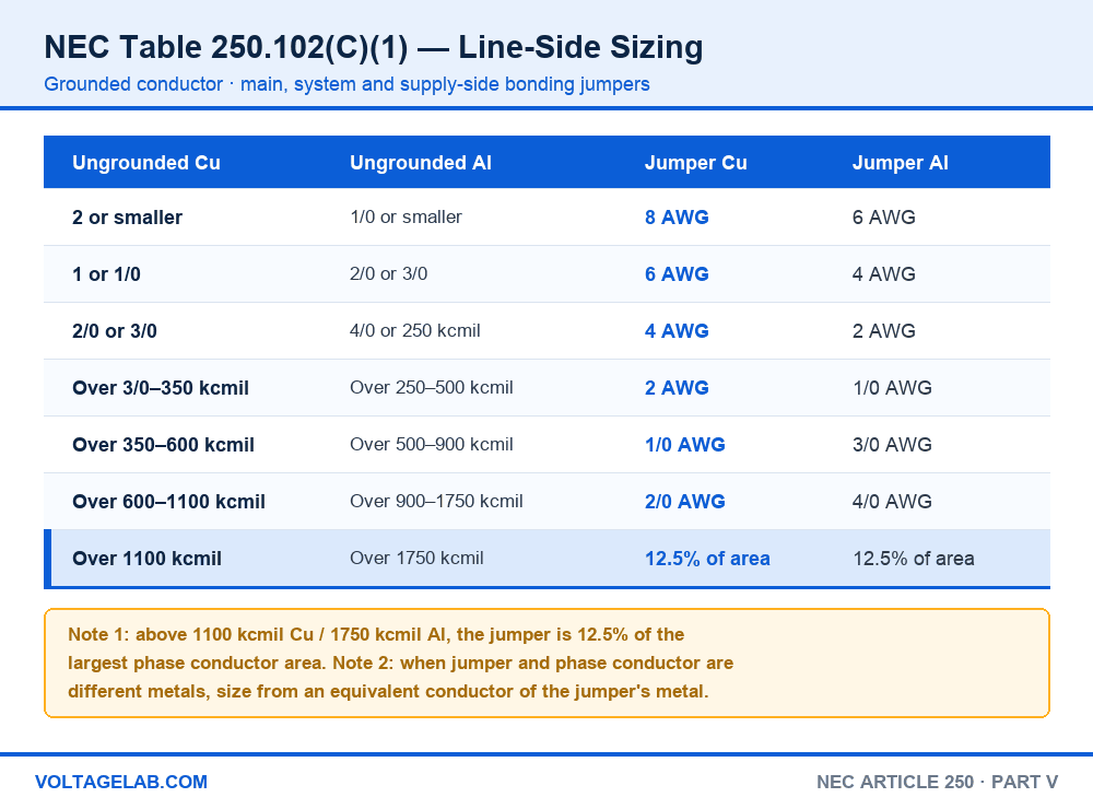
250.102(C) is the line-side size. A supply-side bonding jumper of the wire type is sized from Table 250.102(C)(1), using the largest ungrounded supply conductor in the raceway:
| Largest ungrounded conductor — copper | Largest ungrounded conductor — aluminium | Jumper, copper | Jumper, aluminium |
|---|---|---|---|
| 2 AWG or smaller | 1/0 AWG or smaller | 8 AWG | 6 AWG |
| 1 or 1/0 AWG | 2/0 or 3/0 AWG | 6 AWG | 4 AWG |
| 2/0 or 3/0 AWG | 4/0 AWG or 250 kcmil | 4 AWG | 2 AWG |
| Over 3/0 through 350 kcmil | Over 250 through 500 kcmil | 2 AWG | 1/0 AWG |
| Over 350 through 600 kcmil | Over 500 through 900 kcmil | 1/0 AWG | 3/0 AWG |
| Over 600 through 1100 kcmil | Over 900 through 1750 kcmil | 2/0 AWG | 4/0 AWG |
| Over 1100 kcmil | Over 1750 kcmil | 12.5% of phase area | 12.5% of phase area |
250.102(D) is the load-side size, and it points at Table 250.122 instead — the same table you use for an equipment grounding conductor, based on the rating of the overcurrent device ahead of the equipment. Where a single jumper bonds two or more raceways, size it from the largest overcurrent device supplying circuits in them. The jumper is never required to be larger than the circuit conductors it is protecting.
| OCPD rating | Copper | Aluminium | OCPD rating | Copper | Aluminium |
|---|---|---|---|---|---|
| 15 A | 14 AWG | 12 AWG | 600 A | 1 AWG | 2/0 AWG |
| 20 A | 12 AWG | 10 AWG | 800 A | 1/0 AWG | 3/0 AWG |
| 60 A | 10 AWG | 8 AWG | 1000 A | 2/0 AWG | 4/0 AWG |
| 100 A | 8 AWG | 6 AWG | 1200 A | 3/0 AWG | 250 kcmil |
| 200 A | 6 AWG | 4 AWG | 1600 A | 4/0 AWG | 350 kcmil |
| 300 A | 4 AWG | 2 AWG | 2000 A | 250 kcmil | 400 kcmil |
| 400 A | 3 AWG | 1 AWG | 2500 A | 350 kcmil | 600 kcmil |
| 500 A | 2 AWG | 1/0 AWG | 3000 A | 400 kcmil | 600 kcmil |
The four-step method
Step 1 — find the service disconnect. Stand at the enclosure you are bonding and ask whether there is an overcurrent device between it and the utility. If there is not, you are on the line side and everything below changes.
Step 2 — pick your table. Line side: Table 250.102(C)(1), and the input is the largest ungrounded supply conductor. Load side: Table 250.122, and the input is the overcurrent device rating. Never mix them.
Step 3 — read the row. For a 200-amp residential service run in 4/0 aluminium SER or 2/0 copper, Table 250.102(C)(1) gives a 4 AWG copper jumper. For a 200-amp feeder on the load side, Table 250.122 gives a 6 AWG copper jumper. Same amperage, different answer — that is the whole point of the split.
Step 4 — check the material. Note 2 to Table 250.102(C)(1) handles mixed metals: if the supply conductors are aluminium and the jumper is copper, size the jumper from an aluminium conductor of equivalent ampacity rather than reading the aluminium column straight across. Our guide to bare copper ground wire sizing covers the material and installation rules that follow.
The one that catches everyone — parallel raceways: under NEC 250.102(C)(2), where service conductors are run in parallel in two or more raceways, the supply-side bonding jumper in each raceway is sized from Table 250.102(C)(1) using the ungrounded conductors in that raceway — not the total. If instead you run one single jumper that bonds all the raceways together, that jumper is sized from the sum of the circular mil areas of all the ungrounded supply conductors. Two legitimate approaches, two completely different answers, and using the per-raceway size for a common jumper is a real undersize.
Where a bonding jumper is mandatory — and where it is not
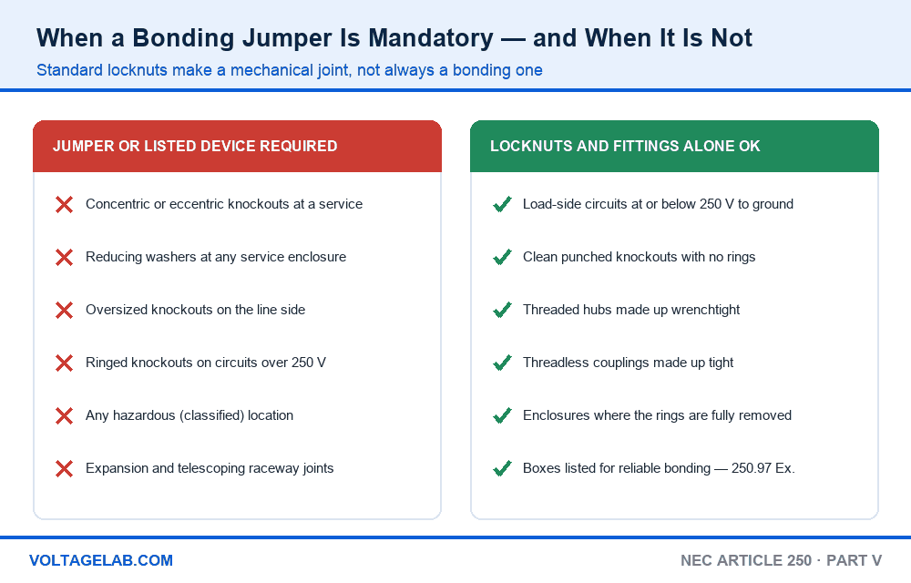
Part V does not require a jumper at every raceway entry. It requires one wherever the ordinary hardware cannot be trusted to carry fault current.
A jumper or a listed bonding device is required
- Concentric or eccentric knockouts at any service enclosure — 250.92(B)
- Oversized knockouts and reducing washers on the line side — 250.92(B)
- Ringed knockouts on circuits over 250 volts to ground — 250.97
- Any raceway or enclosure in a hazardous (classified) location, at any voltage — 250.100
- Expansion fittings and telescoping raceway sections — 250.98
- Enclosures and raceways containing the grounding electrode conductor — 250.92(A)
Standard fittings alone are acceptable
- Load-side circuits at or below 250 volts to ground, into clean punched knockouts
- Threaded hubs and threaded couplings made up wrenchtight
- Threadless couplings and connectors made up tight on metal raceway and metal-clad cable
- Service enclosures where every concentric and eccentric ring has been removed and the locknut bears on solid metal
- Outlet boxes specifically listed to provide reliable bonding at ringed knockouts — the 250.97 exception
Installing the jumper — 250.102(E)
Inside a raceway, the jumper follows 250.120 and 250.148 like any other equipment grounding conductor. Outside a raceway is where the restriction bites: under 250.102(E)(2), a jumper installed outside the raceway or enclosure must not exceed 6 feet (1.8 m) in length and must be routed with the raceway. A jumper looping across the back of a gear lineup to a convenient lug is a violation even if the wire size is right.
The exception covers outdoor pole locations: jumpers installed for bonding isolated sections of metal raceway or elbows in exposed risers are not limited in length and need not be routed with the raceway.
Table 250.102(C)(1) vs Table 250.122 vs Table 250.66
Three tables in Article 250 take a conductor size or a breaker size and hand you back a wire size, and mixing them up is the single most common Article 250 error on exams and on the job:
| Question | Table 250.102(C)(1) | Table 250.122 | Table 250.66 |
|---|---|---|---|
| What it sizes | Grounded conductor, MBJ, SBJ, SSBJ | EGC and load-side EBJ | Grounding electrode conductor |
| What you look up | Largest ungrounded supply conductor | Overcurrent device rating | Largest ungrounded service conductor |
| Which side | Line side | Load side | Service and electrode system |
| Caps out at | 1100 kcmil Cu, then 12.5% | 6000 A | 3/0 Cu for rod, pipe and plate |
| 200 A service example | 4 AWG Cu | 6 AWG Cu | 4 AWG Cu to a water pipe |
If you are working the electrode side of the system rather than the bonding side, start with Table 250.66 and grounding electrode conductor sizing and our overview of the eight grounding electrodes in NEC 250.52. For the load-side conductor itself, see equipment grounding conductors, and for transformer secondaries, grounding and bonding separately derived systems.
Bonding bushing or bonding locknut — which to reach for
Both satisfy 250.92(B)(4). The choice is practical, not legal, and it comes down to whether you need a lug.
Bonding bushing — pros
- Has a set screw and a lug, so you can land an actual jumper and route it to the bar
- Protects the conductors at the raceway end as well as bonding it
- Works on any knockout condition, including reducing washers
- Gives the inspector something visible to sign off
- Accepted for hazardous locations under 250.100 when listed for it
Bonding bushing — cons
- Needs room inside the can for the bushing and the jumper run
- Costs more per entry than a bonding-type locknut
- The jumper still has to be sized and terminated correctly, so it adds a step you can get wrong
A bonding-type locknut is faster and cheaper where the knockout is the only problem and you do not need to run a conductor anywhere. Where you need a wire — a supply-side bonding jumper back to the neutral bar, or a jumper around a reducing washer — the bushing is the tool.
Working with Part V in the field
Do
- Establish where the service disconnect is before you size a single jumper
- Knock out every concentric ring you are not using, so the locknut bears on solid steel
- Scrape paint and powder coat at threads and contact surfaces — 250.96(A)
- Torque every lug and set screw to the marked value with a calibrated tool
- Treat 277/480 V gear as service-grade for bonding purposes at ringed knockouts
Avoid
- Sizing a supply-side bonding jumper from the breaker rating
- Leaving double locknuts as the only bonding at a ringed service knockout
- Running a jumper more than 6 feet outside the raceway
- Using the per-raceway size for a single jumper bonding parallel raceways
- Assuming a hazardous location gets a pass because the circuit is only 120 V
Frequently asked questions
What does NEC 250.90 require?
That bonding be provided wherever it is necessary to ensure electrical continuity and the capacity to safely conduct any fault current likely to be imposed. It is a performance rule — contact alone is not enough if the connection cannot carry the available fault current.
Is a bonding jumper required at every service knockout?
No. It is required around impaired connections — concentric knockouts, eccentric knockouts, oversized knockouts and reducing washers. If the knockout is clean and the locknut bears on solid metal, the double-locknut connection is one of the permitted methods under 250.92(B).
What size supply-side bonding jumper do I need for a 200-amp service?
For 2/0 copper or 4/0 aluminium supply conductors, Table 250.102(C)(1) gives 4 AWG copper or 2 AWG aluminium. Size from the conductors in the raceway, not from the 200-amp rating.
What is the difference between 250.102(C) and 250.102(D)?
(C) covers supply-side bonding jumpers on the line side of the service disconnect and sizes them from Table 250.102(C)(1) using the supply conductors. (D) covers equipment bonding jumpers on the load side and sizes them from Table 250.122 using the overcurrent device rating.
Can a bonding jumper be installed outside the conduit?
Yes, but under 250.102(E)(2) it is limited to 6 feet in length and must be routed with the raceway. The exception for bonding isolated raceway sections and elbows at outdoor pole risers has no length limit and does not have to follow the raceway.
Do 480-volt circuits need bonding bushings?
Where ringed knockouts are present, yes — NEC 250.97 requires one of the methods in 250.92(B)(2) through (B)(4) for circuits over 250 volts to ground. A 277/480 V system is over 250 volts to ground, so a plain double-locknut connection into a ringed knockout does not satisfy it.
How do I size a bonding jumper for parallel service raceways?
Under 250.102(C)(2), a jumper in each individual raceway is sized from Table 250.102(C)(1) based on the ungrounded conductors in that raceway. A single jumper bonding all the raceways together is sized from the sum of the circular mil areas of every ungrounded supply conductor.
Does bonding in a hazardous location depend on voltage?
No. NEC 250.100 applies regardless of the voltage of the system. Every raceway and enclosure in a classified location must be bonded by one of the methods in 250.92(B)(2) through (B)(4), and standard locknuts and bushings cannot be the bonding means.
The bottom line
Part V of Article 250 earns its length because a bonding path that merely exists is not the same as one that works. NEC 250.90 sets that bar, 250.92 through 250.100 mark out the specific hardware the Code refuses to trust, and 250.102 tells you how big the conductor has to be and where you are allowed to run it.
Two restraints do most of the work in the field. First, decide which side of the service disconnect you are on before you open a table, because Table 250.102(C)(1) and Table 250.122 will both give you a plausible answer and only one of them is right. Second, stop treating a tight locknut as a bond at a ringed knockout — on the line side, on 480 volts, or in a classified location, it is not one. For the wider picture of how the electrode system, the grounded conductor and the bonding path fit together, start with our NEC Article 250 overview, and check what changed in the 2026 NEC before you quote a section number on a plan review.
FREE PRACTICE TOOL
Think you'd pass this on a real exam?
Test what you just read with instant-feedback quizzes built around real code questions — not generic trivia.
5
Code standards
10,000+
Active learners
100%
Free to start
Instant explanations on every answer, right or wrong
NEC, BS7671, AS/NZS, CEC, and DIN VDE covered
Bite-sized quizzes you can finish in 5 minutes
No signup required to try your first quiz
No account needed · Takes less than 2 minutes