


Walk onto any UK site and ask who has a lock-off kit in their bag. Most hands go up. Then ask who proved their voltage indicator on a proving unit the last time they isolated a circuit, and who proved it again afterwards. The room goes quiet. Safe isolation is the procedure every electrician says they follow, and the one most likely to be cut short when the job is running late.
That shortcut is where people get hurt. The breaker that was switched off but never locked gets switched back on by someone looking for their kettle. The tester with a flat battery reads “dead” on a live conductor. The neutral that was borrowed from another circuit bites the moment you disconnect it. Isolation fails at the step that was skipped, rarely at the one that was done.
Study smarter with VoltageLab
Built for electricians, apprentices, and electrical engineers who want faster practice and better exam prep.
⭐️ Join thousands of electricians upgrading their skills
This guide sets out the safe isolation procedure in the order the industry teaches it, the kit you need, exactly which conductors to test on single-phase and three-phase circuits, what does and does not count as isolation, and how the same procedure is marked in the AM2.
Quick Answer
The safe isolation procedure is: get permission, identify the circuit, prove your voltage indicator on a proving unit, isolate, lock off with a unique key and fit a caution notice, test every conductor combination to confirm the circuit is dead, then prove the indicator again before starting work.
Use a two-pole voltage indicator that meets HSE Guidance Note GS38, not a multimeter or a voltage stick. A single-phase circuit needs 3 tests (L–N, L–E, N–E). A three-phase circuit needs 10. The legal basis is Regulations 12 and 13 of the Electricity at Work Regulations 1989.
Key Takeaways
- A circuit switched off is not isolated. Isolation means it is switched off and secured so nobody else can switch it back on.
- The voltage indicator is proved on a proving unit or known live supply before the dead test and again after it.
- Single-phase circuits need 3 dead tests; three-phase circuits need 10, with the neutral tested every time.
- Multimeters and non-contact voltage sticks are not suitable for proving a circuit dead.
- The padlock key stays with the person doing the work until the work is finished.
- On a TT supply the neutral cannot be trusted to sit at earth potential, so isolation must break line and neutral together.
What safe isolation means under UK law and BS 7671
Safe isolation is a legal duty before it is a college topic. Regulation 12 of the Electricity at Work Regulations 1989 (EAWR) requires suitable means to cut off the supply and to isolate equipment, and requires that inadvertent reconnection is prevented. Regulation 13 requires adequate precautions so that equipment made dead does not become charged while you work on it. Regulation 14 makes dead working the normal method: live work is allowed only when it is unreasonable to work dead, reasonable to work live, and suitable precautions are in place.
Study smarter with VoltageLab
Built for electricians, apprentices, and electrical engineers who want faster practice and better exam prep.
Join thousands of electricians upgrading their skills
HSE’s guidance on those regulations is HSR25, and its practical guidance on working safely is HSG85. On the installation side, BS 7671 deals with isolation and switching in Chapter 46 and with the selection of isolating devices in Section 537. The day-to-day procedure electricians follow comes from the industry’s Best Practice Guide on safe isolation, produced with the HSE, the IET and the main trade bodies.
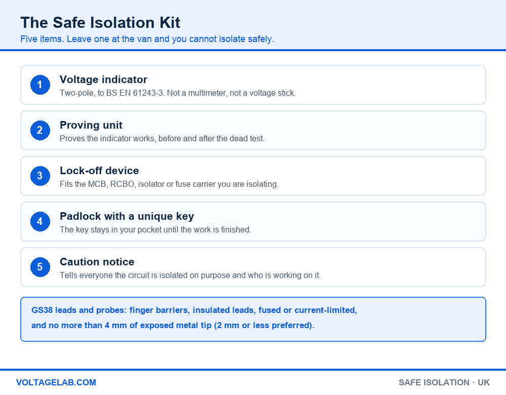
The kit: what each item is for
- Voltage indicator. A two-pole tester or test lamp made to BS EN 61243-3, with leads and probes that meet GS38. This is the only instrument you prove dead with.
- Proving unit. A small battery unit that generates a voltage the indicator can see. It lets you prove the indicator works without hunting for a live socket.
- Lock-off device. A clip, hasp or insert that fits the breaker, isolator or fuse carrier and takes a padlock.
- Padlock with a unique key. One lock, one key, kept by the person doing the work.
- Caution notice. A label at the point of isolation saying the circuit is isolated on purpose and must not be switched on.
GS38 sets out what test leads and probes should look like: finger barriers, well-insulated leads, fused or current-limited protection, and no more than 4 mm of exposed metal at the probe tip, with 2 mm or less preferred. Shrouded probes from the manufacturer satisfy this. A pair of loose meter leads from the bottom of the bag usually does not.
The safe isolation procedure, step by step
The order matters as much as the steps. Each one closes a gap the one before it leaves open.
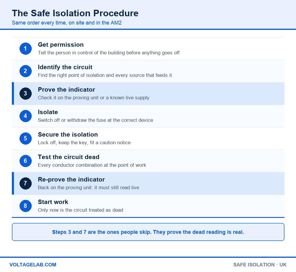
- Get permission. Speak to the person in control of the premises before you switch anything off. On a commercial job that may be the site manager or facilities team. Turning off a circuit that feeds a server, a freezer room or a fire alarm panel without warning creates a new hazard.
- Identify the circuit and every source. Use the circuit chart, then confirm it. Look for anything that can feed the same equipment from elsewhere: a second board, a generator, solar PV, a battery or a borrowed neutral.
- Prove the voltage indicator. Check it on the proving unit or a known live supply. Check the leads and probes for damage at the same time.
- Isolate. Switch off the correct device, or withdraw the fuse, at the point of isolation for that circuit.
- Secure the isolation. Fit the lock-off device and padlock, put the key in your pocket, and fit a caution notice. If you removed a fuse, keep it on you.
- Test the circuit dead. At the point of work, test every combination of conductors (see the next section). The indicator should show no voltage on every one.
- Re-prove the voltage indicator. Back to the proving unit. It must still show live. If it does not, every dead reading you just took is worthless.
- Start work. Only now treat the circuit as dead.
Not isolation: a strip of insulating tape over a breaker, a breaker switched off with no lock, or a fuse left on top of the board. The Best Practice Guide names all three as unsafe. Some boards also have slider switches that disconnect a circuit from the busbar; these do not meet the requirements for isolation and should not be used for it.
Proving dead: which conductors to test
Proving dead means testing between every pair of conductors at the point where you will work, not at the board. The neutral and the protective conductor are included, because either can carry a voltage you were not expecting.
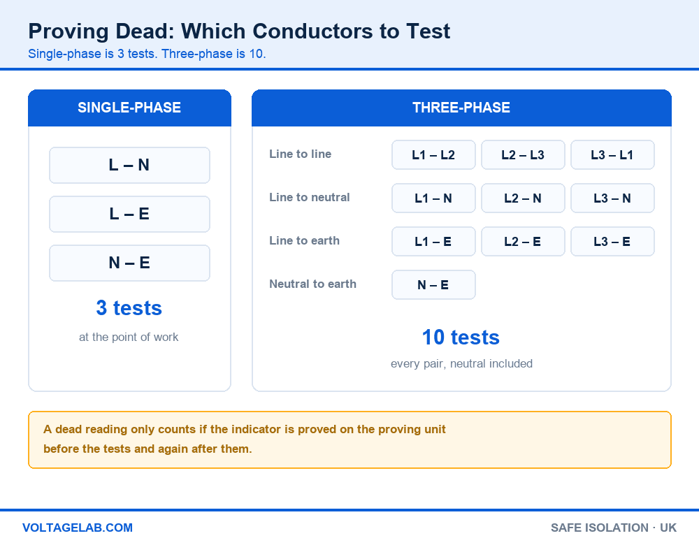
| Supply | Tests | Conductor pairs |
|---|---|---|
| Single-phase | 3 | L–N, L–E, N–E |
| Three-phase (line to line) | 3 | L1–L2, L2–L3, L3–L1 |
| Three-phase (line to neutral) | 3 | L1–N, L2–N, L3–N |
| Three-phase (line to earth) | 3 | L1–E, L2–E, L3–E |
| Three-phase (neutral to earth) | 1 | N–E |
| Three-phase total | 10 | Every pair, neutral included |
How to carry out the dead test
- Prove the indicator on the proving unit and note that every LED or segment lights.
- At the point of work, place the probes on line and neutral. No indication.
- Line and earth. No indication.
- Neutral and earth. No indication.
- On three-phase, work through all ten pairs in the same way, one at a time.
- Return to the proving unit and confirm the indicator still shows live.
The one that catches everyone: the borrowed neutral. BS 7671 does not permit one circuit to use another circuit’s neutral, but it is still found, most often on lighting and control circuits. Isolate one circuit, disconnect its neutral, and the other circuit’s load can make that neutral live. If a neutral shows voltage after isolation, stop and trace it before you go any further.
Isolation devices: what counts and what does not
Every isolation has two parts: a device that can disconnect the circuit, and a way of keeping it disconnected while you work. The device has to be suitable for isolation under BS 7671 Section 537. The second part is what most failures come down to.
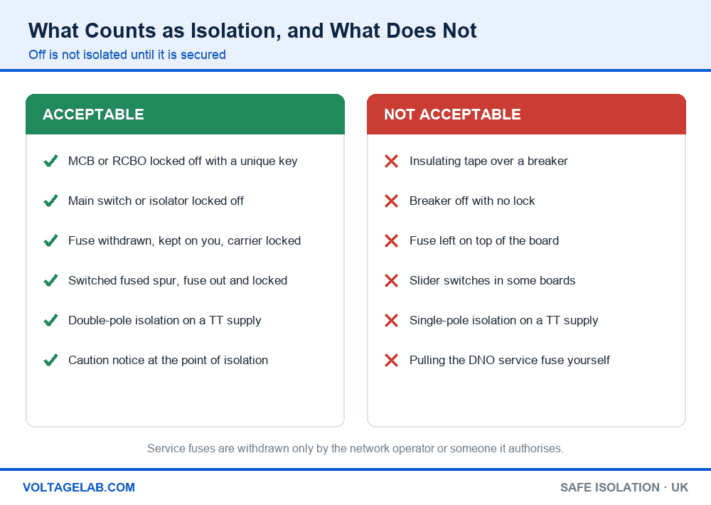
Acceptable means of isolation
- A circuit-breaker or RCBO switched off and locked off with a lock-off device and a padlock with a unique key.
- A main switch or isolator locked in the off position.
- A fuse withdrawn and kept by the person doing the work, with a lockable insert fitted to the carrier.
- A switched fused connection unit with its fuse removed and the carrier locked.
- Where several electricians work from one board, a multi-lock hasp on the main isolator so each person fits their own lock, or each person locking off their own circuits.
Not acceptable
- Tape over a breaker, or a breaker switched off and left unsecured.
- A fuse removed and left near the board where anyone can put it back.
- Slider switches built into some distribution boards.
- Single-pole isolation on a TT or IT supply.
- Withdrawing the distribution network operator’s service fuse yourself, unless you are authorised by the operator to do so.
Why TT supplies need double-pole isolation
On a TN-C-S or TN-S supply the neutral is tied to earth at the supply, so it normally sits close to earth potential. On a TT supply it cannot reliably be treated that way. Isolation on a TT installation must therefore break both line and neutral together, using a double-pole device. Pulling a single-pole fuse or switching a single-pole breaker leaves the neutral connected and is not acceptable. The same applies to all poles of an IT supply.
Voltage indicator vs multimeter vs non-contact tester
All three show voltage. Only one is suitable for proving a circuit dead, and the reasons are about what goes wrong, not about accuracy.
| Question | Two-pole voltage indicator | Multimeter | Non-contact voltage stick |
|---|---|---|---|
| Suitable for proving dead? | Yes | No | No |
| Can be set to the wrong range? | No | Yes | No |
| Tests between two conductors? | Yes | Yes | No |
| GS38 leads and probes as standard? | Yes | Often not | No probes |
| Useful for | Proving dead after isolation | Measurement and fault finding | A first warning that a cable may be live |
A voltage stick has its place. If it lights up, treat the cable as live. If it stays dark, that proves nothing: it can miss a voltage through a metal sheath, a screened cable or a weak battery. A multimeter is a measuring instrument, and a wrong dial setting or a blown internal fuse can show zero on a live conductor. For more on staying safe around conductors, see our guides to safe handling of live wires, preventing shocks on site, PPE for electrical work and lockout/tagout, the North American name for the same locking principle.
Safe isolation in the AM2 and on site
Safe isolation is assessed in the AM2 and AM2S, and assessors watch it closely because a mistake is a safety-critical failure. Candidates who pass describe the same habits: ask permission out loud every time, follow the steps in the same order, never leave the key on the bench, and test every pair even when the answer is obvious. The same habits keep you safe on a Monday morning rewire.
Do
Study smarter with VoltageLab
Built for electricians, apprentices, and electrical engineers who want faster practice and better exam prep.
⭐️ Join thousands of electricians upgrading their skills
- Ask permission before every isolation, including the second and third on the same job.
- Inspect the indicator, leads and probes before you prove them.
- Keep the padlock key and any removed fuse on you.
- Test at the point of work, not only at the board.
- Re-prove the indicator after the dead test, every time.
Avoid
- Trusting the circuit chart without confirming it.
- Using a multimeter or voltage stick to prove dead.
- Skipping the neutral-to-earth test because “the neutral is always dead”.
- Sharing one padlock key between several people.
- Assuming an unidentified cable is dead because nothing is connected to it.
Practise it before the AM2
The VoltageLab app has safe isolation quizzes built on BS 7671 and the UK procedure above, plus 18th Edition practice questions and inspection and testing drills. Choose BS 7671 as your standard when you open it.
Frequently asked questions
What is the correct order for safe isolation?
Permission, identify, prove the indicator, isolate, lock off and fit a notice, test dead, re-prove the indicator, then start work. The two proving steps are the ones most often missed, and they are the ones that make the dead test trustworthy.
How many tests are needed to prove a three-phase circuit dead?
Ten: three line-to-line, three line-to-neutral, three line-to-earth and one neutral-to-earth. A single-phase circuit needs three: line to neutral, line to earth and neutral to earth.
Can I use a multimeter to prove a circuit dead?
No. Industry guidance based on GS38 says multimeters should not be used for proving dead. A wrong range, a blown internal fuse or unsuitable leads can give a zero reading on a live conductor. Use a two-pole voltage indicator made for the job.
Is switching off the breaker enough?
No. EAWR Regulation 12 requires that inadvertent reconnection is prevented. A breaker that is only switched off can be switched back on by anyone. Lock it off, keep the key and fit a caution notice.
What is a proving unit for?
It produces a known voltage so you can confirm your voltage indicator works before and after the dead test. Without it, a faulty indicator and a dead circuit look exactly the same.
Who can remove the DNO service fuse?
Only the distribution network operator or someone it has expressly authorised. If a job such as a consumer unit change needs the incoming supply disconnected, arrange it with the operator rather than pulling the fuse yourself.
What does GS38 require for test probes?
Finger barriers, adequately insulated leads, fused or current-limited protection, and a maximum of 4 mm of exposed metal at the tip, with 2 mm or less preferred. Most manufacturers supply shrouded probes that meet it.
What if more than one person is working on the same board?
Each person must control their own isolation. Use a multi-lock hasp on the main isolator so every worker fits their own padlock, or have each person lock off the circuits they are working on. Nobody should rely on someone else’s lock.
The bottom line
Safe isolation is short, and every step earns its place. The lock and notice stop someone else switching the circuit back on. The dead test confirms the right circuit is off. Proving the indicator before and after confirms the dead test is real. Leave out any one of them and the procedure no longer protects you.
Carry the full kit, follow the same order every time, and treat any unexpected voltage, especially on a neutral, as a reason to stop. For the background on why earth faults behave the way they do, read our guide to earthing rules in installations, and for what each protective device does, see how circuit-breakers work and types of fuse.
FREE PRACTICE TOOL
Think you'd pass this on a real exam?
Test what you just read with instant-feedback quizzes built around real code questions — not generic trivia.
5
Code standards
10,000+
Active learners
100%
Free to start
Instant explanations on every answer, right or wrong
NEC, BS7671, AS/NZS, CEC, and DIN VDE covered
Bite-sized quizzes you can finish in 5 minutes
No signup required to try your first quiz
No account needed · Takes less than 2 minutes