


Every underground feeder job reaches the same moment. The trench is open, the sweeps are glued, and somebody asks how many 4/0 will fit in the 3 inch. Half the crew reaches for a phone app, one guy says “four, always four,” and nobody opens the book. Four is right for Schedule 40. It is wrong for Schedule 80, and that is the kind of miss that gets caught after the concrete goes down.
Conduit fill trips people up because the limit is not a single number and the chart is not a single chart. NEC Chapter 9 Table 1 sets the percentage, Table 4 gives each raceway its internal area, Table 5 gives each conductor its area, and Annex C turns all three into a finished count — but only when every conductor in the pipe is the same size. Schedule 40 and Schedule 80 PVC share a trade size and do not share an inside diameter, so they never share a column.
Study smarter with VoltageLab
Built for electricians, apprentices, and electrical engineers who want faster practice and better exam prep.
⭐️ Join thousands of electricians upgrading their skills
This guide gives you the PVC conduit fill chart for both Schedule 40 and Schedule 80 with THHN/THWN-2, shows where the numbers come from in Chapter 9, walks the calculation for mixed conductor sizes, and covers the Article 352 rules that decide where the pipe is legal in the first place.
Quick Answer
A PVC conduit fill chart gives the maximum number of same-size conductors permitted in a given trade size of rigid PVC. The limit comes from NEC Chapter 9 Table 1: 53% of the internal area for one conductor, 31% for two, and 40% for three or more. Published counts for PVC live in NEC Annex C, Table C.10 for Schedule 40 and Table C.9 for Schedule 80.
The numbers you use day to day: 1 inch Schedule 40 PVC holds 25 × 12 AWG THHN, 2 inch holds 99, and 2 inch holds four 4/0. Schedule 80 has a thicker wall and roughly 17–20% less usable area at the same trade size, so the same 1 inch pipe drops to 20 × 12 AWG. If the conductors in the raceway are not all the same size, the chart does not apply and you calculate from Chapter 9 Table 5 instead.
Key Takeaways
- NEC Chapter 9 Table 1 sets conduit fill at 53% for one conductor, 31% for two, and 40% for three or more — the percentages are of the raceway’s internal cross-sectional area, not its diameter
- Annex C Table C.10 covers Rigid PVC Schedule 40 and HDPE; Table C.9 covers Rigid PVC Schedule 80 — using the wrong table overfills the pipe by about one conductor in five
- Annex C is only valid when every conductor in the raceway is the same size and the same insulation type
- For mixed sizes, add the Table 5 areas of every conductor and keep the total at or below 40% of the Table 4 internal area
- Equipment grounding and bonding conductors count toward conduit fill even though they are not counted as current-carrying for derating
- A conduit nipple 24 inches or shorter may be filled to 60% under Chapter 9 Note 2, and no derating applies to it
- NEC 352.44 requires an expansion fitting once thermal movement in a straight run reaches 0.25 inch — PVC moves about 0.4 inch per 100 feet for every 10 °F of temperature swing
What conduit fill actually limits — NEC Chapter 9 Table 1
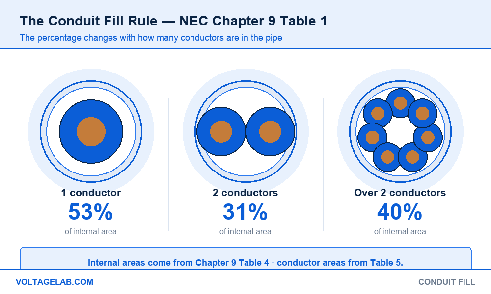
Fill is a cross-sectional area problem. Take the inside area of the pipe, take the total area of everything you are putting in it, and the second number must stay under a fixed percentage of the first. NEC Chapter 9 Table 1 sets that percentage by conductor count:
Pass your electrical exam the first time
Practice real NEC exam questions with full code-referenced explanations and progress tracking — built for journeyman, master and apprentice exam prep.
Thousands of NEC practice questions with code-referenced answers
- 1 conductor — 53%. A single conductor sits in the middle and has room around it.
- 2 conductors — 31%. Two round conductors in a round pipe waste the most space, so the allowance drops.
- Over 2 conductors — 40%. The number that governs almost every real circuit you will ever pull.
Three tables feed the answer. Chapter 9 Table 4 gives the internal area of every raceway in square inches, broken out by type — and rigid PVC gets separate blocks for Schedule 40, Schedule 80, Type A and Type EB. Chapter 9 Table 5 gives the approximate area of each insulated conductor by size and insulation type. Annex C is the pre-solved version of both, for the single case where every conductor is identical.
Why the limit is 40% and not something higher
The 40% figure is not about whether the wire physically fits. Jam ratio, pulling tension and heat all get worse long before the pipe is full. Above 40% the conductors bind on the bends, the jacket abrades, and the air space that lets a bundle shed heat disappears. The ampacity values in Table 310.16 assume that air space exists.
Fill and derating are separate obligations and people collapse them constantly. Staying under 40% does not exempt you from the adjustment factors in 310.15(C)(1) once more than three current-carrying conductors share the raceway. You can pass fill and still be over on ampacity.
Schedule 40 vs Schedule 80 PVC — why the charts differ
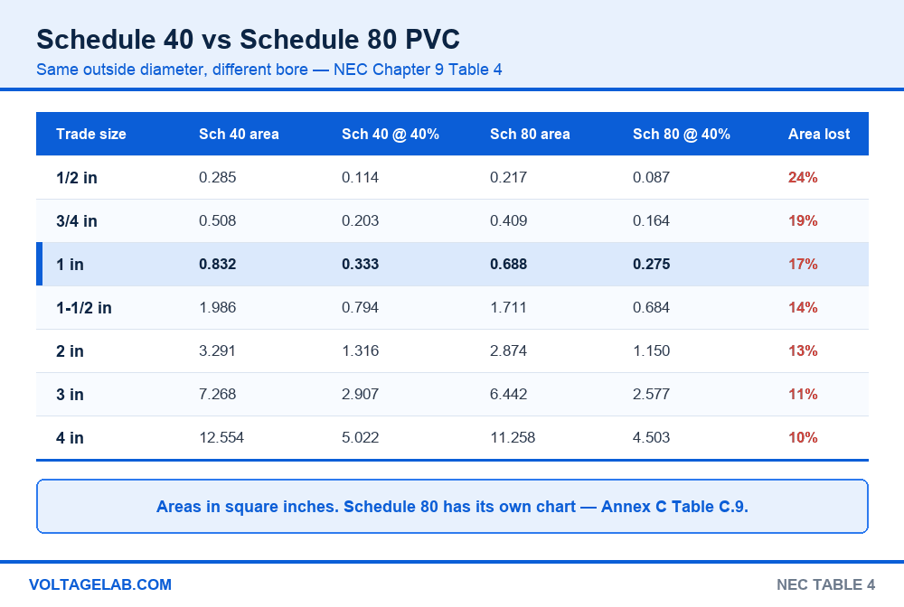
Both schedules share the same outside diameter at a given trade size, because both have to accept the same fittings. Schedule 80 gets its physical-damage rating from a thicker wall, and that wall is taken out of the inside. The result is a pipe that looks identical on the rack and holds noticeably less:
| Trade size | Sch 40 area | Sch 40 at 40% | Sch 80 area | Sch 80 at 40% | Area lost |
|---|---|---|---|---|---|
| 1/2 in | 0.285 | 0.114 | 0.217 | 0.087 | 24% |
| 3/4 in | 0.508 | 0.203 | 0.409 | 0.164 | 19% |
| 1 in | 0.832 | 0.333 | 0.688 | 0.275 | 17% |
| 1-1/2 in | 1.986 | 0.794 | 1.711 | 0.684 | 14% |
| 2 in | 3.291 | 1.316 | 2.874 | 1.150 | 13% |
| 3 in | 7.268 | 2.907 | 6.442 | 2.577 | 11% |
| 4 in | 12.554 | 5.022 | 11.258 | 4.503 | 10% |
Areas are from NEC Chapter 9 Table 4, Article 352 Rigid PVC Conduit. The penalty is worst in the small sizes, where the wall thickness is a bigger share of the bore — a 1/2 inch Schedule 80 loses nearly a quarter of its usable area, while a 4 inch loses about a tenth.
The schedule trap: Annex C Table C.10 is Schedule 40 only. Schedule 80 has its own table, C.9, and the counts are lower in every row. Pulling a Schedule 40 count through Schedule 80 pipe is the single most common PVC fill violation, and it is invisible after the trench is backfilled. Schedule 80 is what you install wherever the conduit is exposed to physical damage under NEC 352.10(F), which means the riser off a pole or up a wall is exactly where the mistake gets made.
PVC conduit fill chart — Schedule 40, THHN/THWN-2
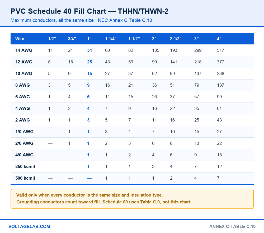
This is the chart most electricians are looking for: maximum number of THHN/THWN-2 conductors, all the same size, in Rigid PVC Schedule 40. It corresponds to NEC Annex C Table C.10.
| Wire size | 1/2″ | 3/4″ | 1″ | 1-1/4″ | 1-1/2″ | 2″ | 2-1/2″ | 3″ | 4″ |
|---|---|---|---|---|---|---|---|---|---|
| 14 AWG | 11 | 21 | 34 | 60 | 82 | 135 | 193 | 299 | 517 |
| 12 AWG | 8 | 15 | 25 | 43 | 59 | 99 | 141 | 218 | 377 |
| 10 AWG | 5 | 9 | 15 | 27 | 37 | 62 | 89 | 137 | 238 |
| 8 AWG | 3 | 5 | 9 | 16 | 21 | 36 | 51 | 79 | 137 |
| 6 AWG | 1 | 4 | 6 | 11 | 15 | 26 | 37 | 57 | 99 |
| 4 AWG | 1 | 2 | 4 | 7 | 9 | 16 | 22 | 35 | 61 |
| 3 AWG | 1 | 1 | 3 | 6 | 8 | 13 | 19 | 30 | 51 |
| 2 AWG | 1 | 1 | 3 | 5 | 7 | 11 | 16 | 25 | 43 |
| 1 AWG | — | 1 | 1 | 3 | 5 | 8 | 12 | 18 | 32 |
| 1/0 AWG | — | 1 | 1 | 3 | 4 | 7 | 10 | 15 | 27 |
| 2/0 AWG | — | 1 | 1 | 2 | 3 | 6 | 8 | 13 | 22 |
| 3/0 AWG | — | 1 | 1 | 1 | 3 | 5 | 7 | 11 | 18 |
| 4/0 AWG | — | — | 1 | 1 | 2 | 4 | 6 | 9 | 15 |
| 250 kcmil | — | — | 1 | 1 | 1 | 3 | 4 | 7 | 12 |
| 350 kcmil | — | — | — | 1 | 1 | 2 | 3 | 5 | 9 |
| 500 kcmil | — | — | — | 1 | 1 | 1 | 2 | 4 | 7 |
PVC conduit fill chart — Schedule 80, THHN/THWN-2
Same conductors, same percentages, smaller pipe. This corresponds to NEC Annex C Table C.9:
| Wire size | 1/2″ | 3/4″ | 1″ | 1-1/4″ | 1-1/2″ | 2″ | 2-1/2″ | 3″ | 4″ |
|---|---|---|---|---|---|---|---|---|---|
| 14 AWG | 9 | 17 | 28 | 51 | 70 | 118 | 170 | 265 | 464 |
| 12 AWG | 6 | 12 | 20 | 37 | 51 | 86 | 124 | 193 | 338 |
| 10 AWG | 4 | 7 | 13 | 23 | 32 | 54 | 78 | 122 | 213 |
| 8 AWG | 2 | 4 | 7 | 13 | 18 | 31 | 45 | 70 | 123 |
| 6 AWG | 1 | 3 | 5 | 9 | 13 | 22 | 32 | 51 | 89 |
| 4 AWG | 1 | 1 | 3 | 6 | 8 | 14 | 20 | 31 | 54 |
| 3 AWG | 1 | 1 | 3 | 5 | 7 | 12 | 17 | 26 | 46 |
| 2 AWG | — | 1 | 2 | 4 | 6 | 10 | 14 | 22 | 39 |
| 1 AWG | — | 1 | 1 | 3 | 4 | 7 | 10 | 16 | 29 |
| 1/0 AWG | — | 1 | 1 | 2 | 3 | 6 | 9 | 14 | 24 |
| 2/0 AWG | — | — | 1 | 1 | 3 | 5 | 7 | 11 | 20 |
| 3/0 AWG | — | — | 1 | 1 | 2 | 4 | 6 | 9 | 17 |
| 4/0 AWG | — | — | 1 | 1 | 1 | 3 | 5 | 8 | 14 |
| 250 kcmil | — | — | — | 1 | 1 | 3 | 4 | 6 | 11 |
| 350 kcmil | — | — | — | 1 | 1 | 1 | 3 | 5 | 8 |
| 500 kcmil | — | — | — | — | 1 | 1 | 2 | 3 | 6 |
When the conductors are not all the same size — the five-step calculation
The moment your raceway holds two different sizes — three 2/0 phases and a 4 AWG ground, say — Annex C is off the table and you calculate. This is the method inspectors expect to see on a submittal.
Step 1 — count every conductor going in. Phases, neutral, equipment grounding conductor, isolated ground, control wires. If it occupies space in the pipe, it is in the calculation.
Step 2 — look up each conductor’s area in Chapter 9 Table 5. Use the row for the actual insulation type. THHN/THWN-2 is the smallest common building wire; XHHW-2 and RHH run larger, and substituting them silently can push a borderline pull over the line.
Step 3 — multiply and total. Quantity times area for each size, then add the products. Three 2/0 THHN at 0.2223 is 0.6669, plus one 4 AWG THHN at 0.0824, for 0.7493 in².
Study smarter with VoltageLab
Built for electricians, apprentices, and electrical engineers who want faster practice and better exam prep.
⭐️ Join thousands of electricians upgrading their skills
Step 4 — apply the Table 1 percentage. Four conductors means 40%. Divide the total by 0.40 to get the minimum internal area the pipe must have: 0.7493 ÷ 0.40 = 1.873 in².
Step 5 — pick the trade size from Table 4. Schedule 40 at 1-1/2 inch is 1.986 in², which clears it. Schedule 80 at 1-1/2 inch is 1.711 in², which does not — that run needs 2 inch. Same conductors, same trench, one trade size apart.
The one that catches everyone: the equipment grounding conductor counts toward conduit fill but is not counted as a current-carrying conductor for derating. Chapter 9 Note 3 requires grounding and bonding conductors to be included in the fill calculation using their actual dimensions; 310.15(C)(1) excludes them from the conductor count for adjustment factors. Two different counts, two different purposes, and people apply one rule to both questions all the time.
Where NEC Article 352 allows PVC conduit — and where it does not
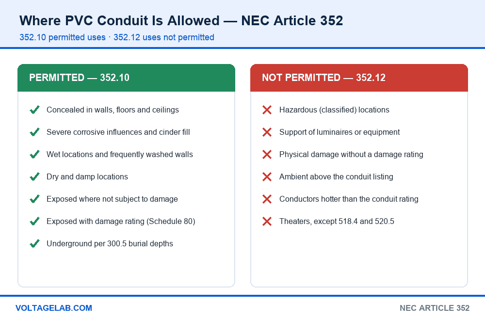
Rigid PVC conduit is covered by NEC Article 352. It is a complete raceway, but unlike steel it is not a ground path — 352.60 requires a wire-type equipment grounding conductor sized from Table 250.122 wherever equipment grounding is needed, and that conductor is part of your fill.
Permitted under 352.10
- Concealed in walls, floors and ceilings
- Locations subject to severe corrosive influences and in cinder fill
- Wet locations, including installations where walls are frequently washed
- Dry and damp locations not prohibited elsewhere in the Article
- Exposed where not subject to physical damage, if identified for the purpose
- Exposed where subject to physical damage, if identified for that use — this is the Schedule 80 case
- Underground, subject to the burial depths and requirements of 300.5 and 305.15
Not permitted under 352.12
- Hazardous (classified) locations, except where specifically permitted by other articles
- For the support of luminaires or other equipment, except conduit bodies no larger than the largest trade size of the conduit
- Where subject to physical damage, unless identified for that use
- Where the ambient temperature exceeds the conduit’s listed rating
- For conductors whose insulation temperature rating exceeds that of the conduit
- In theaters and similar locations, except as permitted by 518.4 and 520.5
Expansion fittings — the calculation nobody runs
NEC 352.44 requires an expansion fitting in a straight run once the expected length change reaches 0.25 inch. PVC has a coefficient of thermal expansion of roughly 3.38 × 10⁻⁵ in/in/°F, which works out to about 0.4 inch per 100 feet for every 10 °F of temperature change. A 100 foot exposed run seeing a 60 °F annual swing moves roughly 2.4 inches — ten times the threshold. Table 352.44 gives the exact figures; use it rather than eyeballing the run.
Support spacing comes from Table 352.30(B) and is tighter than steel conduit because PVC sags: 3 feet for 1/2 through 1 inch, 5 feet for 1-1/4 through 2 inch, 6 feet for 2-1/2 through 3 inch, 7 feet for 3-1/2 through 5 inch and 8 feet for 6 inch. Every run must also be secured within 3 feet of each box, cabinet or fitting.
PVC vs EMT vs IMC vs RMC — fill compared at 1 inch
Trade size is a naming convention, not a measurement. A 1 inch raceway is not 1 inch of anything in particular, and the usable area behind that label varies by more than 25% across raceway types:
| Raceway (1 in trade size) | Internal area | 40% fill | 12 AWG THHN | 10 AWG THHN | Annex C table |
|---|---|---|---|---|---|
| IMC | 0.959 | 0.384 | 29 | 18 | C.4 |
| RMC | 0.887 | 0.355 | 26 | 17 | C.8 |
| EMT | 0.864 | 0.346 | 26 | 16 | C.1 |
| PVC Schedule 40 | 0.832 | 0.333 | 25 | 15 | C.10 |
| ENT | 0.817 | 0.327 | 24 | 15 | C.2 |
| PVC Schedule 80 | 0.688 | 0.275 | 20 | 13 | C.9 |
Nine conductors separate IMC from Schedule 80 in a pipe both labelled 1 inch. That difference decides trench width, sweep radius and sometimes whether the feeder needs a larger pipe than the estimate allowed for.
For the method behind the published tables, see our walkthrough of sizing conduits and raceways with NEC Annex C, and NEC Chapter 9 Table 8 for the conductor properties that sit underneath it. The conductor itself is covered in our THHN/THWN-2 guide — and the wet rating matters here, because the inside of an underground PVC raceway is a wet location. When the raceway terminates, pull box and junction box sizing takes over from fill, and auxiliary gutters under Article 366 have their own 20% rule. If you are weighing a raceway against a cable assembly, compare with MC cable under Article 330.
Is PVC the right raceway for the run?
Pros
- Will not corrode — the default for underground, coastal and chemical environments
- Cheapest raceway per foot, and solvent-weld joints need no threading or dies
- Light enough that one person can set a 4 inch duct bank run
- Schedule 40 holds nearly as much as EMT at the same trade size
- Permitted in wet locations and in cinder fill without special treatment
Cons
- Never a ground path — every run needs a wire-type EGC that eats fill
- Thermal movement is large enough to require expansion fittings on most exposed runs
- Support spacing is tighter than steel, and the pipe sags between straps in heat
- Schedule 80 costs real fill to get a physical-damage rating
Working with PVC fill in the field
Do
- Read the schedule stamped on the pipe before you look up a count
- Include the equipment grounding conductor in every fill total
- Size underground runs one trade size up when future circuits are likely
- Use Table 5 areas for the insulation you are actually pulling, not for THHN by habit
- Keep the total bends between pull points at 360 degrees or less per 352.26
Avoid
- Using a Schedule 40 count in Schedule 80 pipe
- Reading Annex C when the raceway holds mixed conductor sizes
- Treating a passed fill calculation as proof that no derating is needed
- Omitting expansion fittings on long exposed runs because the pipe is strapped
- Pulling plain THHN with no wet marking through underground PVC
Frequently asked questions
How many 12 AWG THHN fit in 1 inch PVC?
Twenty-five in Schedule 40 and twenty in Schedule 80. The 40% allowance on a 1 inch Schedule 40 is 0.333 in² and a 12 AWG THHN is 0.0133 in², which gives 25. Schedule 80’s smaller bore gives 0.275 in², or 20 conductors.
Which NEC table is the PVC conduit fill chart?
Annex C Table C.10 for Rigid PVC Schedule 40 and HDPE, and Table C.9 for Rigid PVC Schedule 80. Table C.11 covers Type A rigid PVC and Table C.12 covers Type EB. The percentages behind all of them are in Chapter 9 Table 1.
Is conduit fill 40% or 53%?
Both, depending on how many conductors are in the raceway. Chapter 9 Table 1 allows 53% for a single conductor, 31% for exactly two, and 40% for three or more. Almost every circuit you pull falls under the 40% column.
Does the ground wire count toward conduit fill?
Yes. Chapter 9 Note 3 requires equipment grounding and bonding conductors to be included in the fill calculation at their actual dimensions, bare or insulated. They are excluded from the current-carrying conductor count used for derating under 310.15(C)(1), which is a different question.
Can a conduit nipple be filled more than 40%?
Yes. Chapter 9 Note 2 permits a nipple not exceeding 600 mm (24 in) in length between boxes, cabinets and similar enclosures to be filled to 60% of its total cross-sectional area, and the adjustment factors of 310.15(C)(1) do not apply to it.
What is the difference between Schedule 40 and Schedule 80 PVC conduit?
Wall thickness. Both share an outside diameter so they take the same fittings, but Schedule 80’s thicker wall gives it a physical-damage rating under 352.10(F) and takes 10–24% of the usable internal area away, depending on trade size. Schedule 80 has its own Annex C table.
Can I use the Annex C chart if my wires are different sizes?
No. Annex C is built on the assumption that every conductor in the raceway is the same size and insulation type. With mixed sizes you total the Chapter 9 Table 5 areas of every conductor and compare the sum against the Table 1 percentage of the Table 4 internal area.
Does PVC conduit need a separate ground wire?
Yes, wherever equipment grounding is required. PVC is nonmetallic and is not recognised as an equipment grounding conductor in 250.118, so NEC 352.60 requires a wire-type EGC sized from Table 250.122 to be run inside the raceway — and it counts toward your fill.
The bottom line
A PVC conduit fill chart is a shortcut, and like every shortcut it has conditions attached. It is valid when all the conductors are the same size, the same insulation, and the schedule on the chart matches the schedule in the trench. Break any one of those and the honest answer comes from Chapter 9 Tables 1, 4 and 5 with a calculator — which takes about ninety seconds and is what an inspector will ask you to show.
The two restraints worth memorising: Schedule 80 is never Schedule 40, and the ground wire counts toward fill but not toward derating. Get those two right and the rest of the chart takes care of itself. For what changed in the current code cycle, see our summary of the 2026 NEC updates, or compare editions in our NEC code book edition guide.
FREE PRACTICE TOOL
Think you'd pass this on a real exam?
Test what you just read with instant-feedback quizzes built around real code questions — not generic trivia.
5
Code standards
10,000+
Active learners
100%
Free to start
Instant explanations on every answer, right or wrong
NEC, BS7671, AS/NZS, CEC, and DIN VDE covered
Bite-sized quizzes you can finish in 5 minutes
No signup required to try your first quiz
No account needed · Takes less than 2 minutes