


The call comes in about a shop light at the back of a pole barn that dims every time the compressor kicks on. The breaker is fine, the terminations are tight, the wire is 12 AWG on a 20-amp circuit, and every ampacity rule in the book has been followed. Nothing is wrong with the installation except its length. That run is 180 feet from the panel, and roughly nine volts never make it to the far end.
Voltage drop is the one conductor calculation the NEC does not make you do, which is exactly why it gets skipped. NEC 210.19(A) and 215.2(A)(2) mention the 3% and 5% figures in Informational Notes, and under 90.5(C) an Informational Note is explanatory material that is not enforceable as a requirement. An inspector usually cannot fail you for it. The equipment at the end of the run can, and will.
Study smarter with VoltageLab
Built for electricians, apprentices, and electrical engineers who want faster practice and better exam prep.
⭐️ Join thousands of electricians upgrading their skills
This guide covers the voltage drop formula for single-phase, three-phase and DC circuits, where the K constant comes from, three worked examples you can check line by line, maximum-length charts for the common branch circuits, and the two places in the Code where the voltage drop limit really is mandatory.
Quick Answer
The voltage drop formula for a single-phase circuit is VD = (2 × K × I × L) ÷ CM. For three-phase, the 2 becomes 1.732. K is the resistivity constant — 12.9 for copper and 21.2 for aluminium — I is the load current in amps, L is the one-way circuit length in feet, and CM is the conductor’s circular mil area from NEC Chapter 9 Table 8.
To size a conductor instead, rearrange it: CM = (2 × K × I × L) ÷ VD, then go to Table 8 and take the next size up, never down. The targets are 3% on a branch circuit and 5% total for feeder plus branch — recommendations in Informational Notes, not enforceable rules, except under 647.4(D) for sensitive electronic equipment and 695.7 for fire pumps.
Key Takeaways
- Single-phase voltage drop is VD = 2KIL ÷ CM; three-phase replaces the 2 with 1.732, because a three-phase circuit does not use a full return path
- K is 12.9 for copper and 21.2 for aluminium — aluminium drops roughly 64% more voltage than copper of the same size
- L is always the one-way distance; the multiplier in the formula already accounts for the return conductor
- The 3% branch and 5% total figures live in Informational Notes, which NEC 90.5(C) says are not enforceable requirements
- NEC 647.4(D) mandates 1.5% branch and 2.5% total for sensitive electronic equipment, and 695.7 sets hard limits for fire pump circuits
- Passing ampacity and passing voltage drop are separate tests — a 12 AWG conductor is legal on a 20-amp circuit at any length, and useless at 180 feet
- When you upsize conductors for voltage drop, NEC 250.122(B) requires the wire-type equipment grounding conductor to be increased proportionately
What voltage drop is and where it comes from
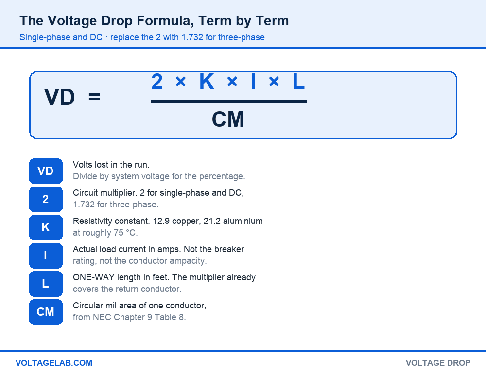
Every conductor is a resistor. Push current through it and some of the supply voltage is spent getting to the load instead of arriving at it. That loss is voltage drop, it is Ohm’s law with a long lever arm, and it scales with three things you control: how much current, how far, and how much copper.
Pass your electrical exam the first time
Practice real NEC exam questions with full code-referenced explanations and progress tracking — built for journeyman, master and apprentice exam prep.
Thousands of NEC practice questions with code-referenced answers
The consequences are not cosmetic. Motors starved of voltage draw more current to make the same torque, run hotter and fail early. Incandescent and some LED sources dim visibly. Electronic power supplies drop out during inrush elsewhere on the system. And the energy that never reached the load left as heat inside the raceway.
Reading the formula, term by term
- VD — the drop, in volts. Divide by the system voltage and multiply by 100 to get a percentage.
- 2 or 1.732 — the circuit multiplier. Single-phase and DC use 2 because current travels out and back. Three-phase uses the square root of 3 because the phases return through each other.
- K — resistivity in ohm-circular mils per foot: about 12.9 for copper and 21.2 for aluminium at 75 °C.
- I — the actual load current in amps. Not the breaker size, and not the conductor ampacity.
- L — the one-way length in feet, from the source to the farthest point of use.
- CM — circular mil area of one conductor, straight out of NEC Chapter 9 Table 8. A 12 AWG is 6,530; a 2 AWG is 66,360.
The single term that trips people is L. Measuring the loop and then applying the multiplier double-counts the return path and doubles your answer. Measure one way and let the formula do the rest. Chapter 9 Table 8 is also where the circular mil figures come from — our guide to NEC Chapter 9 Table 8 walks through the rest of that table.
Single-phase, three-phase and DC — which formula to use
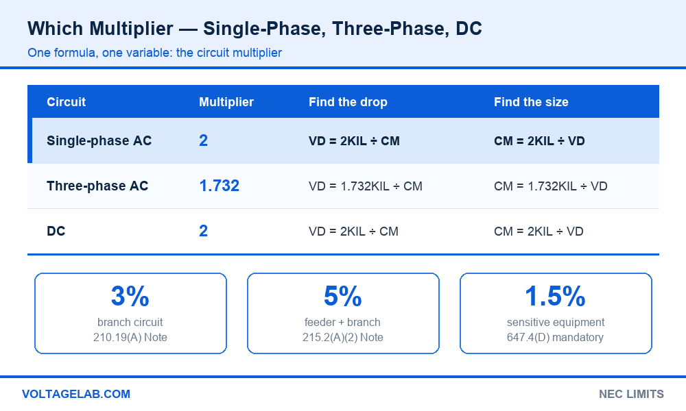
There is one formula with one variable multiplier. Pick the multiplier from the circuit, not from the load:
| Circuit | Multiplier | Find the drop | Find the size | Voltage used for % |
|---|---|---|---|---|
| Single-phase AC | 2 | VD = 2KIL ÷ CM | CM = 2KIL ÷ VD | 120 V or 240 V |
| Three-phase AC | 1.732 | VD = 1.732KIL ÷ CM | CM = 1.732KIL ÷ VD | 208 V, 480 V line-to-line |
| DC | 2 | VD = 2KIL ÷ CM | CM = 2KIL ÷ VD | Nominal DC voltage |
A common mistake on three-phase work is running the single-phase formula on one leg and then correcting it. Do not. Use 1.732 with the line-to-line voltage and the line current, and the answer is the line-to-line drop directly.
The rule that is not a rule: the 3% and 5% figures everyone quotes appear in Informational Notes to 210.19(A) and 215.2(A)(2). NEC 90.5(C) states that Informational Notes are explanatory and not enforceable as requirements of the Code. So an inspector generally cannot red-tag a run for voltage drop alone — but the equipment manufacturer’s listed voltage range still applies under 110.3(B), and a job spec, a local amendment or an energy code can and often does make 3% contractual. Check what governs your job before deciding it does not matter.
How to calculate voltage drop — three worked examples
Example 1 — a 120 V branch circuit that passes ampacity and fails voltage drop
A 12-amp load sits 100 feet from the panel on a 120-volt, 20-amp circuit wired in 12 AWG copper. Ampacity is not in question. Voltage drop is.
- VD = (2 × 12.9 × 12 × 100) ÷ 6,530
- VD = 30,960 ÷ 6,530 = 4.74 volts
- 4.74 ÷ 120 = 3.95% — over the 3% target
Step up to 10 AWG, circular mil area 10,380: VD = 30,960 ÷ 10,380 = 2.98 volts, or 2.48%. One size up solves it, and the breaker stays at 20 amps.
Example 2 — sizing a three-phase feeder from scratch
An 80-amp, 208-volt three-phase feeder runs 220 feet to a subpanel. Copper. Target 3%. Here you solve for the conductor instead of checking one.
- Allowable drop: 208 × 0.03 = 6.24 volts
- Required area: CM = (1.732 × 12.9 × 80 × 220) ÷ 6.24
- CM = 393,233 ÷ 6.24 = 63,018 circular mils
- Table 8 lookup: 3 AWG is 52,620 — too small. 2 AWG is 66,360 — take it.
- Verify: 393,233 ÷ 66,360 = 5.93 volts = 2.85% ✓
Always round up to the next standard size. Rounding down to 3 AWG gives 3.59% and defeats the reason you ran the calculation. For the rules governing the feeder itself, see NEC Article 215.
Example 3 — what aluminium costs you
A 50-amp, 240-volt single-phase subpanel feed runs 175 feet in 6 AWG.
- Copper (K = 12.9): (2 × 12.9 × 50 × 175) ÷ 26,240 = 8.60 V = 3.58%
- Aluminium (K = 21.2): (2 × 21.2 × 50 × 175) ÷ 26,240 = 14.14 V = 5.89%
Same size, same run, and the aluminium drops 64% more. Neither one meets 3%, but the copper needs one size up and the aluminium needs two or three. That is the trade you are making when the material switches on a long run.
The five-step method
Step 1 — get the real current. Use the calculated load, or motor full-load current from Table 430.248 or 430.250. The breaker rating is not the load.
Study smarter with VoltageLab
Built for electricians, apprentices, and electrical engineers who want faster practice and better exam prep.
⭐️ Join thousands of electricians upgrading their skills
Step 2 — measure one way. Source to the farthest outlet or the equipment terminals, following the actual raceway path including risers and drops.
Step 3 — set the target in volts. System voltage times the percentage. 240 V at 3% is 7.2 V. On a feeder plus branch, split the 5% budget deliberately rather than spending it all in one place.
Step 4 — run the formula. Solve for VD if you have a conductor in mind, or for CM if you are picking one.
Step 5 — take the next size up and re-check everything else. A larger conductor changes conduit fill, may change the lug and termination, and triggers 250.122(B) on the grounding conductor.
The one that catches everyone: when you increase the ungrounded conductors above the size ampacity required, NEC 250.122(B) requires the wire-type equipment grounding conductor to be increased proportionately in circular mil area. Upsize 12 AWG to 10 AWG for voltage drop and the 12 AWG ground goes up too. This one is a mandatory rule, not an Informational Note, and it is missed on the majority of voltage-drop upsizes.
Maximum circuit length charts for a 3% drop
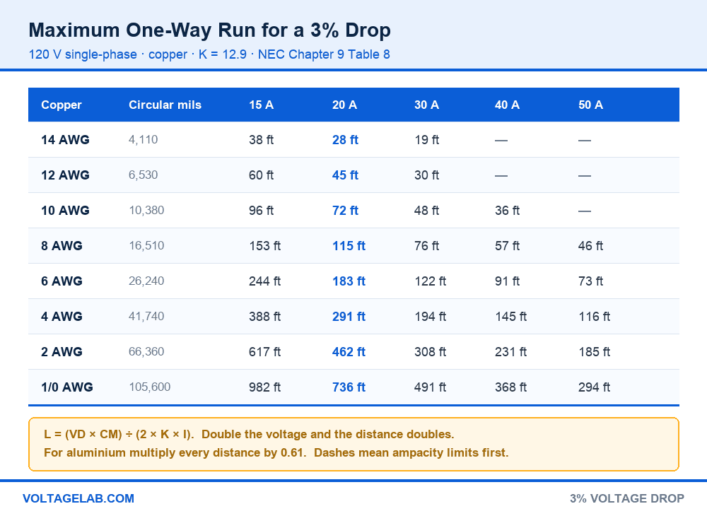
Most of the time you are not solving an equation, you are asking whether this run is too long. These charts answer that directly: the maximum one-way distance, in feet, before a copper conductor exceeds 3% at a given load.
| Copper size | Circular mils | 15 A | 20 A | 30 A | 40 A | 50 A |
|---|---|---|---|---|---|---|
| 14 AWG | 4,110 | 38 ft | 28 ft | 19 ft | — | — |
| 12 AWG | 6,530 | 60 ft | 45 ft | 30 ft | — | — |
| 10 AWG | 10,380 | 96 ft | 72 ft | 48 ft | 36 ft | — |
| 8 AWG | 16,510 | 153 ft | 115 ft | 76 ft | 57 ft | 46 ft |
| 6 AWG | 26,240 | 244 ft | 183 ft | 122 ft | 91 ft | 73 ft |
| 4 AWG | 41,740 | 388 ft | 291 ft | 194 ft | 145 ft | 116 ft |
| 2 AWG | 66,360 | 617 ft | 462 ft | 308 ft | 231 ft | 185 ft |
| 1/0 AWG | 105,600 | 982 ft | 736 ft | 491 ft | 368 ft | 294 ft |
Double the voltage and you double the distance, which is why 240-volt circuits reach so much further on the same wire:
| Copper size | 20 A | 30 A | 40 A | 50 A | 60 A | 100 A |
|---|---|---|---|---|---|---|
| 12 AWG | 91 ft | 60 ft | — | — | — | — |
| 10 AWG | 144 ft | 96 ft | 72 ft | — | — | — |
| 8 AWG | 230 ft | 153 ft | 115 ft | 92 ft | — | — |
| 6 AWG | 366 ft | 244 ft | 183 ft | 146 ft | 122 ft | — |
| 4 AWG | 582 ft | 388 ft | 291 ft | 232 ft | 194 ft | — |
| 2 AWG | 925 ft | 617 ft | 462 ft | 370 ft | 308 ft | 185 ft |
| 1/0 AWG | 1,473 ft | 982 ft | 736 ft | 589 ft | 491 ft | 294 ft |
| 2/0 AWG | 1,857 ft | 1,238 ft | 928 ft | 742 ft | 619 ft | 371 ft |
| 4/0 AWG | 2,952 ft | 1,968 ft | 1,476 ft | 1,181 ft | 984 ft | 590 ft |
Where the NEC actually requires a voltage drop limit
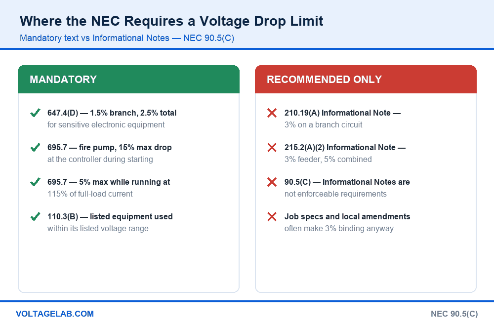
Two places in the Code state a voltage drop limit in mandatory language, and they are both worth knowing because they come up on jobs where nobody expects them.
Mandatory
- NEC 647.4(D) — sensitive electronic equipment on separately derived 120/240 V technical power: branch circuit drop not over 1.5%, and combined branch plus feeder not over 2.5%.
- NEC 695.7 — fire pumps: the voltage at the controller line terminals shall not drop more than 15% below normal during motor starting, and not more than 5% below the controller’s rated voltage while running at 115% of full-load current.
- NEC 110.3(B) — indirectly, but with teeth. Listed equipment must be used per its listing, and the listing includes an operating voltage range. Starve it and you are outside the listing.
Recommended only
- 210.19(A) Informational Note — 3% on a branch circuit to the farthest outlet
- 215.2(A)(2) Informational Note — 3% on a feeder, 5% for feeder and branch combined
- Both are explanatory material under 90.5(C) and are not enforceable as Code requirements
- Local amendments, energy codes and project specifications frequently convert them into hard limits — that is where the obligation usually comes from
The 3% and 5% budget, split properly
The 5% is a total, not a second allowance. If a feeder to a subpanel already burns 3%, the branch circuits downstream get 2%, not another 3%. On long runs, spend the budget where the current is highest — the feeder — because that is where an extra conductor size buys the most volts back per dollar.
K-constant method vs the Chapter 9 Table 9 method
The K formula is an approximation that ignores reactance and assumes a unity power factor. For most branch circuits and short feeders that error is trivial. For long runs, large conductors or low power factor loads, the exact method in Chapter 9 Table 9 gives a truer answer, using effective impedance and the actual power factor:
| Method | Source | Accounts for | Best for | Effort |
|---|---|---|---|---|
| K constant | Table 8 circular mils | Resistance only | Branch circuits, exams, field checks | One line |
| Table 8 resistance | DC resistance per 1,000 ft | Resistance, DC or short AC | DC circuits, PV strings | One line |
| Table 9 effective Z | AC R and X per 1,000 ft | Resistance, reactance, power factor, raceway type | Long feeders, 1/0 and up, motor loads | Several steps |
Table 9 also breaks its values out by raceway type, because a steel raceway adds inductive reactance that PVC does not. If you are running large conductors in steel over a long distance, that difference is real and the K method will read optimistic.
Related reading on the inputs this calculation depends on: minimum circuit ampacity for getting the load current right, THHN/THWN-2 ratings for the conductor you are sizing, equipment grounding conductors for the 250.122(B) upsize, multi-wire branch circuits where the neutral current is not what you assume, and PVC conduit fill for the raceway you just outgrew. If you are studying rather than installing, our voltage drop exam question guide covers the patterns that show up on the Journeyman test.
Is upsizing the conductor the right fix?
Pros
- Always works, and costs nothing in labour if caught before the pull
- Recovers the wasted energy permanently — the loss was heat
- Leaves headroom for load growth on the same run
- Reduces motor heating and extends equipment life at the far end
- One size up is usually enough — drop falls roughly 37% per step
Cons
- Copper cost rises faster than the voltage you recover
- Triggers 250.122(B), so the grounding conductor grows too
- May push the raceway or the terminations up a size
- Does nothing for a run that is long because it was routed badly
Before adding copper, check the alternatives: shorten the route, move the panel closer to the load, or raise the utilisation voltage. A 240-volt circuit does the same work at half the current and a quarter of the drop, which is why long shop and outbuilding feeds are run at 240 and stepped down locally. Our transformer sizing guide covers that last option.
Working with voltage drop in the field
Do
- Run the calculation at rough-in, while the wire is still on the reel
- Use actual load current, not breaker size or conductor ampacity
- Measure the real raceway path, including every riser and drop
- Upsize the equipment grounding conductor along with the phases
- Check the job spec — it often sets a tighter limit than the NEC
Avoid
- Doubling the length and keeping the 2 in the formula
- Rounding down to the nearest conductor size
- Spending the full 3% on the feeder and again on the branch
- Assuming aluminium behaves like copper one size up — it is closer to two
- Treating a passed ampacity check as a passed voltage drop check
Frequently asked questions
What is the voltage drop formula?
VD = (2 × K × I × L) ÷ CM for single-phase and DC, and VD = (1.732 × K × I × L) ÷ CM for three-phase. K is 12.9 for copper and 21.2 for aluminium, I is load current, L is the one-way length in feet, and CM is circular mils from NEC Chapter 9 Table 8.
Does the NEC require 3% voltage drop?
Not as a general rule. The 3% branch and 5% total figures appear in Informational Notes to 210.19(A) and 215.2(A)(2), and NEC 90.5(C) says Informational Notes are not enforceable requirements. It becomes mandatory under 647.4(D) for sensitive electronic equipment, under 695.7 for fire pumps, and wherever a local amendment or job specification adopts it.
Is L the one-way or round-trip distance?
One way. The multiplier of 2 in the single-phase formula already accounts for the current travelling out and back. Using the round-trip distance with that multiplier doubles your answer and sends you two conductor sizes larger than you need.
Why is the three-phase multiplier 1.732 instead of 2?
Because a balanced three-phase circuit has no dedicated return conductor — each phase returns through the other two. The square root of 3, about 1.732, is the factor that relates line-to-line voltage to the per-phase drop in that arrangement.
How far can I run 12 AWG on a 20-amp circuit?
About 45 feet at 120 volts before a full 20-amp load exceeds 3%, and roughly 91 feet at 240 volts. At a lighter actual load the distance stretches proportionally — 12 amps instead of 20 gets you to about 75 feet at 120 volts.
Where does the K value of 12.9 come from?
It is the approximate resistivity of copper in ohm-circular mils per foot at about 75 °C. Aluminium is roughly 21.2 at the same temperature. Both are approximations — the exact resistance figures are in Chapter 9 Table 8, and the exact AC impedance values are in Table 9.
Do I have to upsize the ground wire when I upsize for voltage drop?
Yes. NEC 250.122(B) requires wire-type equipment grounding conductors to be increased proportionately in circular mil area whenever the ungrounded conductors are increased above the minimum size required for ampacity. Unlike the 3% figure, this one is enforceable.
Does voltage drop affect the breaker size?
No. Overcurrent protection is sized for the load and the conductor’s ampacity under Article 240, not for voltage drop. Upsizing 12 AWG to 10 AWG to fix a long run leaves the breaker at 20 amps — the bigger conductor is there for volts, not amps.
The bottom line
Voltage drop is the calculation that separates a circuit that is legal from a circuit that works. One formula covers every case — 2KIL over CM, with 1.732 in place of the 2 for three-phase — and it takes less time to run than the phone call you get six months later about the lights dimming.
Two restraints are worth memorising: L is always one way, and the answer always rounds up to the next conductor size. Then remember that upsizing drags the equipment grounding conductor along with it under 250.122(B). For the code changes worth tracking in the current cycle, see our summary of what changed in the 2026 NEC.
FREE PRACTICE TOOL
Think you'd pass this on a real exam?
Test what you just read with instant-feedback quizzes built around real code questions — not generic trivia.
5
Code standards
10,000+
Active learners
100%
Free to start
Instant explanations on every answer, right or wrong
NEC, BS7671, AS/NZS, CEC, and DIN VDE covered
Bite-sized quizzes you can finish in 5 minutes
No signup required to try your first quiz
No account needed · Takes less than 2 minutes