

A multi-wire branch circuit (MWBC) lets you run two 120V circuits with three conductors instead of four. That sounds like a simple efficiency gain — and it is, when installed correctly. But a miswired or misunderstood MWBC is one of the most dangerous wiring configurations in a building. An open neutral on a shared circuit has killed electricians who believed the circuit was de-energized.
This guide covers every NEC requirement for multi-wire branch circuits under NEC Article 210, including the 2023 code clarification on circuit origination, the simultaneous disconnect requirement, the line-to-neutral load restriction, the grouping rule, and the neutral continuity requirement that protects both workers and equipment.
Study smarter with VoltageLab
Built for electricians, apprentices, and electrical engineers who want faster practice and better exam prep.
⭐️ Join thousands of electricians upgrading their skills
Here is what we cover:
- What a multi-wire branch circuit is and how the neutral current works
- NEC 210.4 requirements: origination, disconnecting means, load type, grouping
- NEC 300.13(B): the neutral continuity rule and why it matters
- Handle tie vs. common-trip breaker — which is required and when
- The open neutral hazard explained with a real scenario
- Common code violations and inspection failures
Multi-Wire Branch Circuit Quick Reference (NEC 2023)
Table 1: MWBC Requirements at a Glance — NEC Article 210 & 300 (2023 Edition)
| Requirement | NEC Section | What It Requires |
|---|---|---|
| Circuit origination | NEC 210.4(A) | All MWBC conductors must originate from the same equipment where the branch-circuit OCPD is located |
| Simultaneous disconnection | NEC 210.4(B) | A means must be provided to disconnect all ungrounded conductors simultaneously at the point of origin |
| Load type restriction | NEC 210.4(C) | MWBCs must supply only line-to-neutral loads (with two exceptions) |
| Conductor grouping | NEC 210.4(D) | Ungrounded and grounded conductors must be grouped in at least one location at the panelboard |
| Neutral continuity | NEC 300.13(B) | Continuity of the grounded conductor must not depend on device connections — the neutral must be spliced at each device |
| Circuit breaker type | NEC 240.15(B) | 120/240V systems: handle ties permitted. Other systems (208Y/120V, 480Y/277V): common-trip breaker required |
What Is a Multi-Wire Branch Circuit?
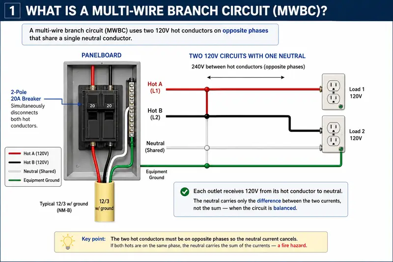
NEC Article 100 defines a multiwire branch circuit as: “A branch circuit that consists of two or more ungrounded conductors that have a voltage between them, and a grounded conductor that has equal voltage between it and each ungrounded conductor of the circuit and that is connected to the neutral or grounded conductor of the system.”
In practical terms, the most common MWBC in residential and light commercial work uses a 3-wire cable (two hot conductors plus a neutral) connected to opposite phases in a 120/240V single-phase panel. The result: two independent 120V circuits that share a single neutral conductor.
How the Neutral Current Works
This is the physics that makes an MWBC work — and what makes it dangerous when wired incorrectly.
In a correctly wired MWBC on a 120/240V single-phase system, the two hot conductors are on opposite legs of the panel (180° out of phase with each other). Because the voltages are opposing, the return currents on the neutral partially cancel. The neutral carries only the difference between the current on each hot conductor — not the sum.
FREE PRACTICE TOOL
Think you'd pass this on a real exam?
Test what you just read with instant-feedback quizzes built around real code questions — not generic trivia.
5
Code standards
10,000+
Active learners
100%
Free to start
Instant explanations on every answer, right or wrong
NEC, BS7671, AS/NZS, CEC, and DIN VDE covered
Bite-sized quizzes you can finish in 5 minutes
No signup required to try your first quiz
No account needed · Takes less than 2 minutes
Table 2: Neutral Current in a Correctly Wired vs. Miswired MWBC (120/240V Single-Phase)
| Scenario | Hot A Current | Hot B Current | Neutral Current | Result |
|---|---|---|---|---|
| Correct — opposite phases | 15A | 10A | 5A (difference) | ✅ Normal — neutral well within capacity |
| Correct — balanced | 15A | 15A | 0A | ✅ Perfect balance — no neutral current at all |
| Miswired — same phase | 15A | 10A | 25A (sum) | ❌ Dangerous — neutral overloaded, fire risk |
If both hot conductors are mistakenly landed on the same phase leg in the panel, the neutral carries the sum of both currents instead of the difference. On a 20A circuit with a 12 AWG neutral, this can push well over the conductor’s ampacity — generating enough heat to ignite nearby combustibles, typically without tripping any breaker because neither hot conductor is overloaded individually.
On a 3-phase 208Y/120V or 480Y/277V system, the MWBC uses three hot conductors (one per phase) and a single neutral. With balanced loads, the neutral current is again minimized because the three-phase currents are 120° apart. However, these systems are sensitive to harmonic currents from non-linear loads (computers, variable frequency drives, LED drivers), which can cause the neutral to carry significantly more current than any individual phase — a point noted in NEC 210.4(A) Informational Note No. 1, which references NEC 310.15(E) for neutral ampacity guidance.
NEC 210.4 — The Four Requirements
210.4(A) — Circuit Origination
All conductors of a multiwire branch circuit must originate from the same equipment containing the branch-circuit overcurrent protective device.
2023 NEC clarification: Previous editions allowed conductors to originate from “the same panelboard or similar distribution equipment.” The 2023 NEC removed the phrase “or similar distribution equipment” because that term is not defined in the NEC. The intent — that all MWBC conductors originate from the same equipment as the OCPD — was always clear, but the 2023 language eliminates any ambiguity.
Exception — NEC 300.3(B)(4): This permits conductors of a multi-wire branch circuit to originate from different panelboard sections when column-width panelboard configurations make a single point of origination impractical. This is a narrow exception for specific equipment configurations, not a general permission to split MWBC conductors across separate panels.
210.4(B) — Simultaneous Disconnecting Means
Each multiwire branch circuit must be provided with a means that will simultaneously disconnect all ungrounded conductors at the point where the branch circuit originates.
This requirement exists because of the open neutral hazard. If only one hot conductor is de-energized, the shared neutral remains part of a live circuit on the other leg. Anyone touching that neutral conductor — believing the circuit is off — can become the fault current return path.
What qualifies as a simultaneous disconnecting means:
- Two-pole or three-pole common-trip circuit breaker — when the handle is operated (or if it trips), both or all poles open simultaneously
- Two single-pole circuit breakers with an identified handle tie — permitted only on 120/240V single-phase systems, per NEC 240.15(B)(1). The handle tie must be a listed device designed for that breaker model.
Important: The simultaneous disconnection requirement applies to the disconnecting means (manual operation). It does not require that the breaker trip both poles simultaneously under fault conditions. NEC 240.15(B) addresses this separately — for systems other than 120/240V, a common-trip multi-pole breaker is required so that an overcurrent on one pole trips the entire breaker.
Table 3: Disconnecting Means Requirements by System Voltage — NEC 210.4(B) and 240.15(B)
| System | Permitted Disconnecting Means | NEC Reference |
|---|---|---|
| 120/240V, single-phase | 2-pole common-trip breaker or two single-pole breakers with listed handle tie | NEC 210.4(B), 240.15(B)(1) |
| 208Y/120V, 3-phase | Multi-pole common-trip breaker required | NEC 210.4(B), 240.15(B)(2) |
| 480Y/277V, 3-phase | Multi-pole common-trip breaker required | NEC 210.4(B), 240.15(B)(2) |
210.4(C) — Line-to-Neutral Loads Only
Unless an exception applies, a multi-wire branch circuit must supply only line-to-neutral loads. It must not be used to supply loads connected between the two hot conductors (line-to-line loads) — for example, a 240V appliance — unless one of the following exceptions is met:
Study smarter with VoltageLab
Built for electricians, apprentices, and electrical engineers who want faster practice and better exam prep.
⭐️ Join thousands of electricians upgrading their skills
- Exception No. 1: The MWBC supplies only one utilization equipment (a single appliance). In that case, the equipment can be a line-to-line load because there is no shared neutral current imbalance risk.
- Exception No. 2: All ungrounded conductors of the MWBC are opened simultaneously by the branch-circuit overcurrent device. If the OCPD opens all poles at once under any condition, line-to-line loads are permitted because complete de-energization is guaranteed.
210.4(D) — Grouping of Conductors
The ungrounded and grounded circuit conductors of each multi-wire branch circuit must be grouped using wire markers, cable ties, or similar means in at least one location within the panelboard or other point of origination.
The purpose is to ensure that anyone working in the panel can identify which neutral belongs to which set of hot conductors, preventing the accidental disconnection of only one leg while leaving the other live on a shared neutral.
Exception — grouping not required when:
- The circuit conductors enter from a cable or raceway unique to that circuit, making the grouping self-evident
- The conductors pass through a box or conduit body without a splice or termination (no work point exists)
NEC 300.13(B) — Neutral Continuity: The Rule That Prevents Electrocution
This is the single most important safety rule for MWBCs. NEC 300.13(B) states that the continuity of a grounded conductor (neutral) on a multi-wire branch circuit must not depend on device connections — such as receptacles, luminaire connections, or other devices where the removal of the device would interrupt continuity.
In plain English: You cannot pigtail the neutral at a device and rely on the device terminals for neutral continuity. If the neutral runs into a receptacle’s silver terminal and back out to continue downstream, removing that receptacle breaks the neutral for every load downstream of it — while the hot conductors remain energized. The result is a floating neutral downstream, which can apply full line-to-line voltage (240V on a 120/240V system) across loads rated for only 120V. Equipment is destroyed. Anyone touching an exposed conductor can be electrocuted.
The correct method: At every device location on an MWBC, the neutral conductor must be spliced — using a wire connector (wire nut or push-in connector) — and a pigtail run to the device terminal. The through-neutral continuity is maintained by the splice, not by the device.
Table 4: NEC 300.13(B) — Correct vs. Incorrect Neutral Wiring at MWBC Devices
| Method | Neutral Through Device Terminals? | Code Compliant? | Risk if Device Removed |
|---|---|---|---|
| Neutral spliced, pigtail to device | No — splice maintains continuity | ✅ Yes — NEC 300.13(B) compliant | None — neutral continuity maintained at splice |
| Neutral looped through device terminals | Yes — device provides continuity | ❌ No — NEC 300.13(B) violation | Open neutral downstream — 240V across 120V loads, electrocution risk |
The Open Neutral Hazard — A Real Scenario
An electrician is replacing a receptacle in a kitchen. The panel has a 2-pole breaker for the MWBC feeding the kitchen countertop circuits. The electrician turns off one pole and tests the receptacle — it reads zero volts. They remove the receptacle and grab the neutral conductor to pigtail it. That neutral is still live at 120V — return current from the other, still-active leg is flowing through it. The electrician receives a severe shock.
This scenario is exactly why NEC 210.4(B) requires simultaneous disconnection of all ungrounded conductors. When the 2-pole breaker is opened, both hot conductors are de-energized simultaneously, and the shared neutral carries no current. The circuit is truly safe to work on.
The same hazard exists during troubleshooting when someone opens one breaker of a handle-tied pair, or when handle ties are missing entirely — which is a common violation in older installations predating the simultaneous disconnect requirement.
MWBC on the Job Site — Where You’ll Find Them
Residential Kitchen Countertop Circuits
NEC 210.52(B)(1) requires at least two small-appliance branch circuits for kitchen countertop receptacles. A single MWBC using 12/3 NM cable can satisfy both circuits — two 20A circuits from one cable run. This is one of the most common legitimate MWBC applications in residential work. The 2-pole 20A breaker and pigtailed neutrals at each receptacle are essential.
Commercial and Industrial Panel Wiring
In commercial 3-phase 208Y/120V panels, MWBCs are commonly used to reduce raceway fill. A single conduit run with three hots (one per phase) and a shared neutral serves three separate 120V circuits. In this configuration, a 3-pole common-trip breaker is required — a handle tie is not sufficient on a 3-phase system.
Legacy Wiring in Existing Buildings
In buildings wired before the simultaneous disconnect requirement became mandatory, you will frequently encounter MWBCs with two single-pole breakers and no handle tie — or with the wrong wiring (both hots on the same phase). Identifying these during service work is important. Key indicators:
- A 3-wire cable (two hots, one neutral, no ground — common in pre-1960s wiring) in a 2-wire area
- Two breakers that, when one is turned off, cause the neutral at a device to still read voltage
- Two single-pole breakers on adjacent positions in the panel but with no handle tie
Common Code Violations on Multi-Wire Branch Circuits
Both Hot Conductors on the Same Phase Leg
This is a wiring error, not a design choice — but it happens during panel changes, circuit extensions, and breaker replacements. Both hots land on the same phase, the neutral carries additive current, and the circuit overheats without any breaker responding. Verify phase relationship with a voltmeter: the voltage between the two hot conductors of an MWBC must be 240V (single-phase) or 208V (3-phase wye), not 0V. Zero volts between the two hots confirms they are on the same phase leg.
No Simultaneous Disconnect (Missing Handle Tie)
Single-pole breakers with no handle tie on a 120/240V MWBC violates NEC 210.4(B). This is extremely common in existing installations. On a 208Y/120V or 480Y/277V system, handle ties are not permitted at all — a common-trip breaker is required per NEC 240.15(B)(2).
Neutral Continuity Dependent on Device
Neutral wired through device terminals without a splice at the device violates NEC 300.13(B). This is common in older work where the installer simply looped the neutral conductor through the receptacle terminals to save time. Replace with a proper splice and pigtail.
Conductors Not Grouped in Panel
Failure to group the ungrounded and grounded conductors of each MWBC at the panelboard violates NEC 210.4(D). Cable ties or wire markers at the point of origin are inexpensive and take seconds to install — there is no justification for skipping this on a new installation.
Line-to-Line Load on MWBC Without Simultaneous Opening
Installing a 240V load (such as a small appliance using both hot conductors) on an MWBC that doesn’t have a common-trip OCPD violates NEC 210.4(C). If only one hot trips, the 240V appliance remains partially energized in an unpredictable state.
Conclusion
A properly installed multi-wire branch circuit is an efficient and fully code-compliant wiring method. An improperly installed one is one of the most hazardous configurations you will encounter in the field. Four rules cover every MWBC installation:
- All conductors originate from the same equipment as the OCPD — per NEC 210.4(A), updated in the 2023 NEC to remove ambiguous language.
- All hot conductors must disconnect simultaneously — 2-pole common-trip or handle-tied single-pole breakers on 120/240V; common-trip only on other systems — per NEC 210.4(B) and 240.15(B).
- Supply only line-to-neutral loads unless both exceptions in NEC 210.4(C) are satisfied.
- Splice the neutral at every device — never depend on a device connection for neutral continuity — per NEC 300.13(B). This rule directly prevents electrocution.
Frequently Asked Questions
What is a multi-wire branch circuit?
A multi-wire branch circuit (MWBC) is a branch circuit consisting of two or more ungrounded (hot) conductors with voltage between them, and a single grounded (neutral) conductor with equal voltage between it and each hot conductor. The definition is in NEC Article 100. The most common configuration in residential work is two 120V hot conductors sharing a single neutral on a 120/240V system, run as 3-wire (plus ground) cable.
Does a multi-wire branch circuit require a 2-pole breaker?
It requires a means of simultaneously disconnecting all ungrounded conductors at the point of origin, per NEC 210.4(B). On a 120/240V system, this can be either a 2-pole common-trip breaker or two single-pole breakers with a listed handle tie (NEC 240.15(B)(1)). On 3-phase systems such as 208Y/120V or 480Y/277V, a multi-pole common-trip breaker is required — handle ties are not permitted for those systems (NEC 240.15(B)(2)).
Why must the neutral be spliced at each receptacle on a multi-wire branch circuit?
NEC 300.13(B) prohibits the continuity of a grounded conductor on an MWBC from depending on device connections. If the neutral runs through a receptacle’s terminal without a splice, removing that receptacle creates an open neutral for everything downstream. On an MWBC, an open neutral leaves the remaining hot conductors energizing downstream loads at full line-to-line voltage — potentially 240V across 120V-rated equipment — and creates a live neutral conductor that poses a severe electrocution risk.
Can a multi-wire branch circuit supply a 240V appliance?
Only under specific conditions. NEC 210.4(C) requires MWBCs to supply line-to-neutral loads. Exceptions permit a line-to-line (240V) load if the MWBC supplies only one piece of equipment (Exception 1), or if all ungrounded conductors are opened simultaneously by the branch-circuit overcurrent device (Exception 2). Outside of these exceptions, 240V loads on an MWBC are a code violation.
How do I identify a multi-wire branch circuit in an existing panel?
Look for: (1) two breakers in adjacent panel positions sharing a handle tie or a 2-pole breaker feeding a 3-conductor cable, (2) a 3-wire cable (two different color hots plus a white neutral) at a receptacle or junction box, or (3) a neutral that still reads voltage after you turn off one breaker. Confirm proper phase relationship by measuring voltage between the two hot conductors — it should be 240V on a single-phase system or 208V on a 3-phase wye system. If it reads 0V, both conductors are on the same phase — a hazardous miswire that must be corrected.
FREE PRACTICE TOOL
Think you'd pass this on a real exam?
Test what you just read with instant-feedback quizzes built around real code questions — not generic trivia.
5
Code standards
10,000+
Active learners
100%
Free to start
Instant explanations on every answer, right or wrong
NEC, BS7671, AS/NZS, CEC, and DIN VDE covered
Bite-sized quizzes you can finish in 5 minutes
No signup required to try your first quiz
No account needed · Takes less than 2 minutes
