



 Scan to install
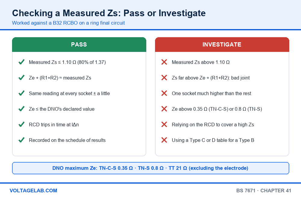
The loop tester reads 1.18 Ω at the far socket of a kitchen ring on a B32 RCBO. The table in your pocket says 1.37 Ω, so it passes. Or does it? Measured cold, at the end of a cable that will run warmer under load, 1.18 Ω is above the 80% figure of 1.10 Ω that most inspectors work to. Whether that circuit passes depends on understanding where the maximum Zs values come from, not just on looking one up.
Max Zs causes trouble because there are several tables, and the right one depends on the device, its type and the disconnection time. The values also changed in 2015 when the minimum voltage factor came in, so older cards and apps still show figures about 5% too high. Compare a cold reading against a value meant for a hot conductor, or read a Type B figure for a Type C breaker, and an unsafe circuit looks compliant.
This guide explains what Zs is and how the maximum is worked out. It gives the max Zs tables for MCBs, RCBOs, fuses and RCDs, explains the 80% rule and when to use a proper temperature correction, and shows how to check a measured reading step by step.
Quick Answer
Max Zs values are the highest earth fault loop impedance a circuit can have and still make its protective device disconnect in the time BS 7671 requires. They are worked out as Zs = U0 × Cmin ÷ Ia, with U0 = 230 V and Cmin = 0.95. They are listed in Tables 41.2 and 41.4 for fuses, Table 41.3 for MCBs and RCBOs, and Table 41.5 for RCDs. For example, a Type B 32 A MCB or RCBO has a maximum Zs of 1.37 Ω.
The tables assume the conductors are at their full operating temperature. A Zs you measure on a cold circuit should therefore be no more than about 80% of the table value, which is 1.10 Ω for a B32.
Key Takeaways
- Zs is the impedance of the whole earth fault loop: Ze from the supply plus R1+R2 of your circuit.
- Max Zs = 230 V × 0.95 ÷ Ia. For MCBs, Ia is 5 × In for Type B, 10 × In for Type C and 20 × In for Type D.
- Values since 2015 include Cmin = 0.95, so they are 5% lower than older cards. B32 went from 1.44 Ω to 1.37 Ω.
- Compare a measured, cold Zs with 80% of the table value, or correct it for conductor temperature first.
- Final circuits up to 63 A with sockets, and up to 32 A for fixed equipment, need 0.4 s on TN systems. Distribution circuits get 5 s.
- An RCD’s maximum Zs is far higher, 1,667 Ω for 30 mA, but readings above about 200 Ω may not be stable.
- A Type D breaker is the hardest to satisfy. D32 allows only 0.34 Ω at 0.4 s.
What Zs is and how BS 7671 sets the maximum
When line touches earthed metalwork, current flows round a loop. It leaves the supply transformer winding, runs through the supply line conductor to your board, out along the circuit’s line conductor to the fault, back along the circuit protective conductor to the main earthing terminal, and back through the supply’s earth return to the transformer. Zs is the impedance of that whole loop. The fault current is roughly U0 ÷ Zs, and the protective device must see enough current to disconnect in time.
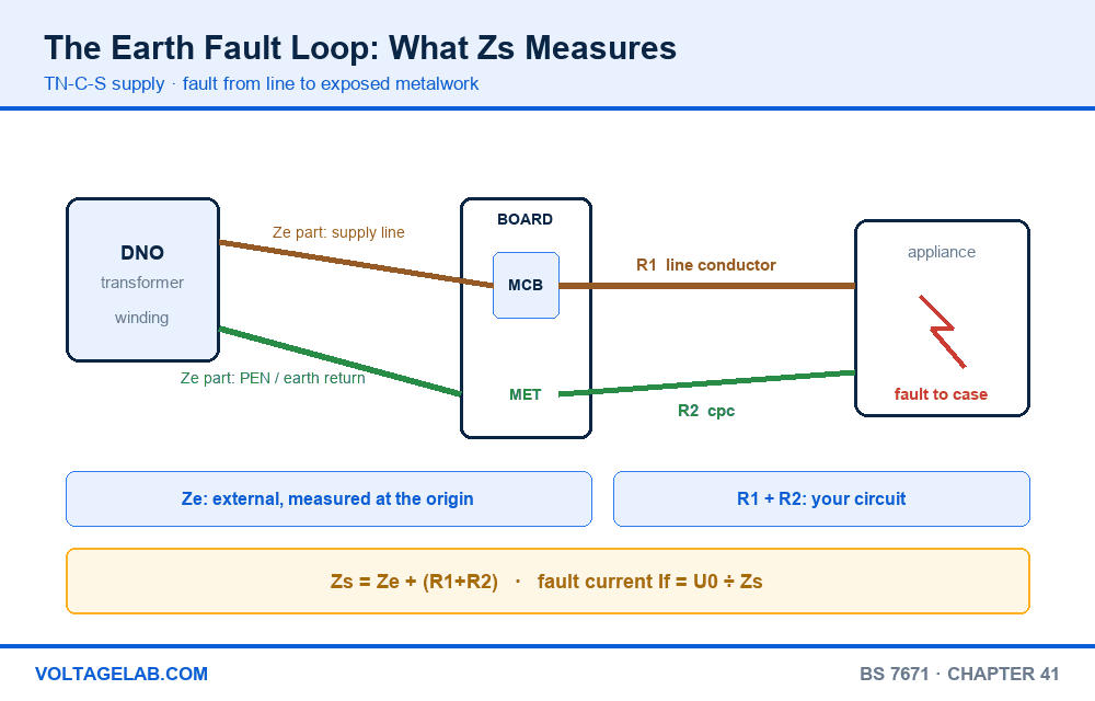
Regulation 411.4.4 sets the condition for a TN system: Zs × Ia ≤ U0 × Cmin. Rearranged, that gives the maximum Zs for any device, Zs = U0 × Cmin ÷ Ia. Ia is the current that makes the device operate within the required time, read from its time-current curve. Cmin is the minimum voltage factor, 0.95 for a supply under the ESQCR. It allows for the supply voltage being below 230 V when the fault happens.
Decoding Ze, Zs, R1+R2, Ia and Cmin
Ze is the external earth fault loop impedance, measured at the origin with the main earthing conductor disconnected. R1+R2 is the resistance of your circuit’s line and protective conductors, from the continuity test. Zs = Ze + (R1+R2), and it is measured live at the furthest point of each circuit. Ia is the operating current of the device for the required disconnection time. Cmin = 0.95. Distributors declare a maximum Ze of 0.35 Ω for TN-C-S (PME), 0.8 Ω for TN-S and 21 Ω for TT, the last excluding your own electrode.
Max Zs for MCBs and RCBOs: Table 41.3
A circuit-breaker to BS EN 60898, or the overcurrent part of an RCBO to BS EN 61009, trips instantly once the fault current reaches its magnetic threshold. That is 5 × In for Type B, 10 × In for Type C and 20 × In for Type D. Because the trip is instantaneous above that point, the 0.4 s and 5 s values are the same for Types B and C. For Type D, BS 7671 gives a separate, higher 5 s value.
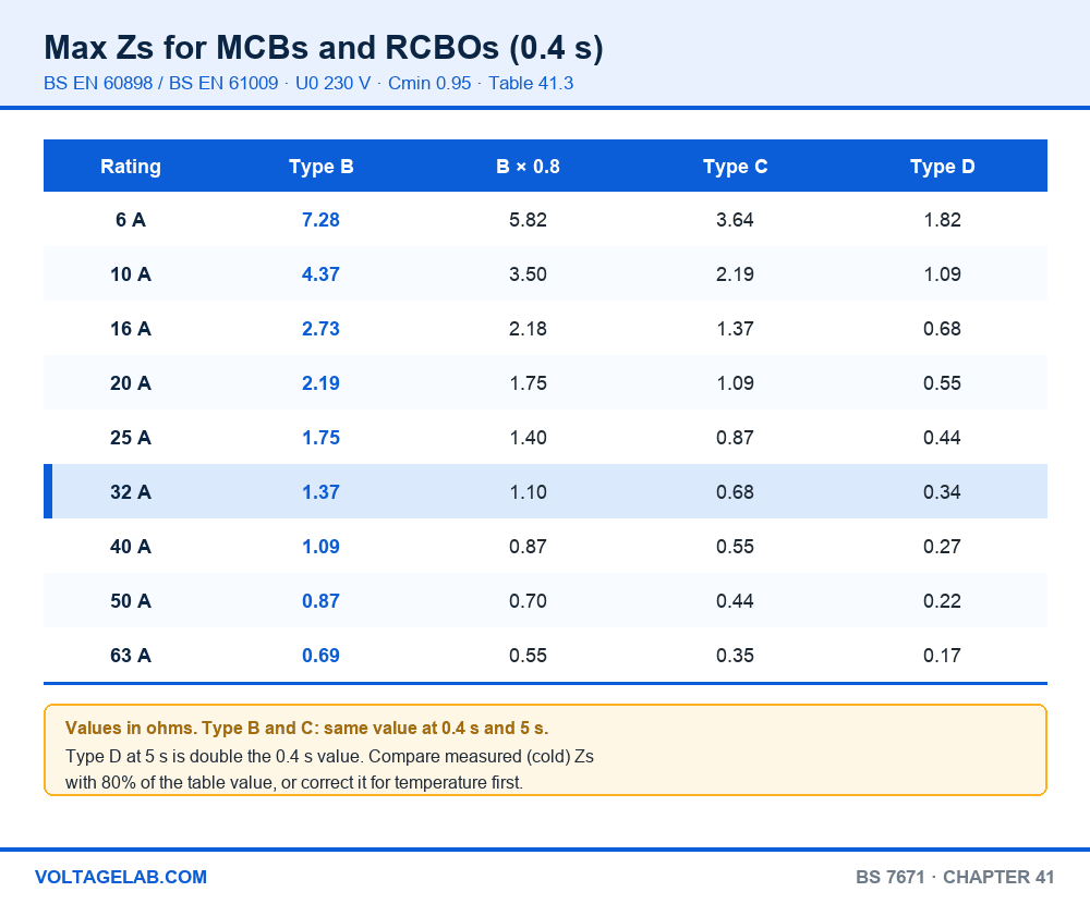
| Rating (A) | Type B | Type B × 0.8 | Type C | Type C × 0.8 | Type D (0.4 s) | Type D × 0.8 |
|---|---|---|---|---|---|---|
| 6 | 7.28 | 5.82 | 3.64 | 2.91 | 1.82 | 1.46 |
| 10 | 4.37 | 3.50 | 2.19 | 1.75 | 1.09 | 0.87 |
| 16 | 2.73 | 2.18 | 1.37 | 1.10 | 0.68 | 0.54 |
| 20 | 2.19 | 1.75 | 1.09 | 0.87 | 0.55 | 0.44 |
| 25 | 1.75 | 1.40 | 0.87 | 0.70 | 0.44 | 0.35 |
| 32 | 1.37 | 1.10 | 0.68 | 0.54 | 0.34 | 0.27 |
| 40 | 1.09 | 0.87 | 0.55 | 0.44 | 0.27 | 0.22 |
| 50 | 0.87 | 0.70 | 0.44 | 0.35 | 0.22 | 0.18 |
| 63 | 0.69 | 0.55 | 0.35 | 0.28 | 0.17 | 0.14 |
| 80 | 0.55 | 0.44 | 0.27 | 0.22 | 0.14 | 0.11 |
| 100 | 0.44 | 0.35 | 0.22 | 0.18 | 0.11 | 0.09 |
| 125 | 0.35 | 0.28 | 0.17 | 0.14 | 0.09 | 0.07 |
Comparing a cold reading with a hot limit: the table values apply with the conductors at their maximum operating temperature, 70 °C for ordinary PVC twin and earth. When you measure Zs, the cable is cold and its resistance is about 20% lower. A B32 ring that measures 1.30 Ω looks fine against 1.37 Ω, but at full load the R1+R2 part rises and the real Zs passes the limit. The breaker may then not trip magnetically and could take seconds to clear the fault. Compare measured values with 80% of the table, or correct R1+R2 for temperature before you add it to Ze. Never compare a cold reading directly with the table.
Max Zs for fuses: Tables 41.2 and 41.4
Fuses have no instantaneous trip, so the current needed to blow one in 0.4 s is much higher than the current that blows it in 5 s. Each fuse therefore has two values. Use Table 41.2 (0.4 s) for final circuits and Table 41.4 (5 s) for distribution circuits.
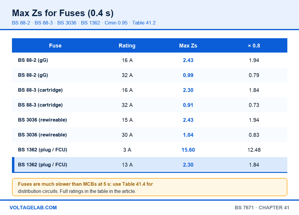
| Rating (A) | BS 88-2 gG 0.4 s | BS 88-2 gG 5 s | BS 88-3 0.4 s | BS 88-3 5 s | BS 3036 0.4 s |
|---|---|---|---|---|---|
| 5 | – | – | 9.93 | 14.6 | 9.10 |
| 6 | 7.80 | 12.0 | – | – | – |
| 10 | 4.65 | 6.80 | – | – | – |
| 15 | – | – | – | – | 2.43 |
| 16 | 2.43 | 4.00 | 2.30 | 3.90 | – |
| 20 | 1.68 | 2.80 | 1.93 | 3.20 | 1.68 |
| 25 | 1.29 | 2.20 | – | – | – |
| 30 | – | – | – | – | 1.04 |
| 32 | 0.99 | 1.70 | 0.91 | 1.60 | – |
| 40 | 0.75 | 1.30 | – | – | – |
| 45 | – | – | 0.57 | 1.00 | 0.56 |
| 50 | 0.57 | 0.99 | – | – | – |
| 63 | 0.44 | 0.78 | 0.36 | 0.68 | – |
How to check a measured Zs, step by step
- Identify the device. Read the type, rating and standard off the breaker or fuse: B32, C16, BS 88-3 30 A and so on.
- Find the disconnection time. Use 0.4 s for a TN final circuit up to 63 A with sockets or up to 32 A for fixed equipment, and 5 s for distribution circuits and larger final circuits (Table 41.1).
- Look up the maximum Zs in the right table for that device and time.
- Take 80% of it as your limit for a measured value, or calculate the temperature correction instead.
- Measure Ze at the origin and R1+R2 from the continuity test, and predict Zs = Ze + (R1+R2).
- Measure Zs live at the furthest point of the circuit, using a no-trip loop test on RCD-protected circuits.
- Compare. The measured value should be close to the prediction and below your 80% limit. A big gap between predicted and measured points to a bad connection somewhere on the loop.
- Record the measured Zs, the device and the maximum value used on the schedule of test results.
The one that catches everyone: an RCBO with a Zs too high for its overcurrent part. Regulation 411.4.5 allows the RCD part to provide fault protection, and a 30 mA RCD will clear an earth fault at almost any realistic Zs. That doesn’t make a high reading acceptable. A high Zs also means a high line-neutral loop, so a short circuit may not trip the breaker magnetically. Treat the Table 41.3 value as the target for the RCBO’s overcurrent part, and investigate any reading above it rather than relying on the RCD to cover it.
RCDs, TT systems and disconnection times
Where an RCD provides fault protection, the condition becomes Zs × IΔn ≤ 50 V, and Table 41.5 gives the resulting maximum Zs. These limits are high because an RCD needs very little current to trip. This is how most TT installations comply, since a TT earth electrode rarely gets near the low values a breaker needs.
| Circuit (U0 230 V) | TN system | TT system | Regulation |
|---|---|---|---|
| Final circuit ≤ 63 A with sockets, or ≤ 32 A fixed equipment only | 0.4 s | 0.2 s | 411.3.2.2, Table 41.1 |
| Distribution circuit, or a larger final circuit | 5 s | 1 s | 411.3.2.3, 411.3.2.4 |
| 30 mA RCD as fault protection | Max Zs 1,667 Ω (50 V ÷ 0.03 A) | Table 41.5 | |
| 100 mA RCD | Max Zs 500 Ω | Table 41.5 | |
| 300 mA RCD | Max Zs 167 Ω | Table 41.5 | |
| 500 mA RCD | Max Zs 100 Ω | Table 41.5 | |
Table 41.5 carries a note that a resistance above 200 Ω may not be stable, because soil dries out and freezes. On a TT installation, aim well below that figure and keep the electrode reading on the certificate. The device ratings above are explained in our guide to the types of MCB, and fuse construction in our guide to the types of fuse and their characteristics. How the protective path is built is covered in the importance of earthing rules and our earthing cable size calculation. For why conductor resistance rises as the cable warms up, see the relationship between resistance and temperature.
The 80% rule or a full temperature correction?
80% rule: pros
- Quick to apply on site from a single table.
- Recognised in BS 7671 Appendix 3 and by the main certification bodies.
- Always errs on the safe side for normal thermoplastic cable.
80% rule: cons
- Applies the reduction to the whole Zs, including Ze, which doesn’t heat up. It can fail a circuit that would pass with a proper correction.
- Doesn’t fit cables with a different operating temperature, such as 90 °C thermosetting.
Use the 80% rule as your everyday check. When a reading is close to the limit, do the correction properly. Multiply the measured R1+R2 by 1.20 for 70 °C thermoplastic cable, add Ze, and compare the total with the full table value. A B32 ring with Ze 0.35 Ω and R1+R2 0.70 Ω measures about 1.05 Ω, which passes the 80% limit of 1.10 Ω. The corrected value is 0.35 + 0.84 = 1.19 Ω, which also passes against 1.37 Ω.
Working with max Zs in the field
Do
- Predict Zs from Ze and R1+R2 before you measure it.
- Read the breaker type off the device, not off the board schedule.
- Use a no-trip loop test on RCD-protected circuits.
- Measure at the furthest point of every circuit.
- Check that your card or app shows post-2015 (Cmin 0.95) values.
Avoid
- Comparing a cold measured Zs with the full table value.
- Using a Type B value for a Type C or D breaker.
- Using a 5 s value for a socket final circuit.
- Accepting a high RCBO reading because the RCD will trip.
- Measuring Ze with the main earth still connected.
Max Zs on your phone
VoltageLab: Electrician App has a BS 7671 Quick Reference with maximum Zs values for MCBs, RCBOs and fuses, plus testing practice questions that make you check a measured reading against the right table. Choose BS 7671 as your standard when you open it.
Frequently asked questions
What is the max Zs for a B32 MCB?
1.37 Ω under BS 7671 Table 41.3, at U0 230 V with Cmin 0.95. The limit for a measured, cold reading under the 80% rule is 1.10 Ω.
What is the max Zs for a B6 lighting circuit?
7.28 Ω for a Type B 6 A MCB or RCBO, or 5.82 Ω for a measured cold reading. For a B10 it is 4.37 Ω, or 3.50 Ω measured.
Why did the max Zs values change?
Amendment 3 of the 17th Edition, in 2015, introduced the minimum voltage factor Cmin = 0.95 to allow for the supply voltage being low when a fault happens. Every value in Tables 41.2 to 41.4 dropped by 5%, and B32 went from 1.44 Ω to 1.37 Ω. The 18th Edition kept those values.
How do I work out max Zs for a device not in the tables?
Use Zs = U0 × Cmin ÷ Ia. Read Ia from the device’s time-current curve at the disconnection time you need. For an MCCB, use the instantaneous trip setting. For example, a 100 A MCCB set to trip instantly at 1,000 A gives 218.5 ÷ 1,000 = 0.22 Ω.
Does a 30 mA RCBO make Zs irrelevant?
No. The RCD part can provide fault protection up to 1,667 Ω, but the breaker part still has to clear short circuits and earth faults that the RCD may not see, such as a line-neutral fault. Aim to meet the Table 41.3 value for the overcurrent part.
What are typical Ze values?
Distributors declare maximums of 0.35 Ω for TN-C-S (PME), 0.8 Ω for TN-S and 21 Ω for TT, excluding the electrode. Measured values are often lower. A Ze above the declared maximum should be reported to the distributor.
The bottom line
Max Zs is a single formula, U0 × Cmin ÷ Ia, worked out for every common device and printed in Tables 41.2 to 41.5. Pick the right table for the device and the disconnection time, take 80% of the value for a cold measurement, and the check is quick. B32 is 1.37 Ω, or 1.10 Ω measured. B6 is 7.28 Ω, or 5.82 Ω measured.
Two habits keep the numbers honest. Predict Zs from Ze and the R1+R2 you measured during the continuity test, so a bad joint shows up as a gap. Don’t let an RCD cover for a high reading on a breaker. Before any live test, run through the safe isolation procedure for the dead tests that come first, and for the bigger picture of why the fault path matters, see grounding and bonding essentials.