


Ask three apprentices what size wire a 30-amp dryer needs and you will usually get three answers, all said with confidence. One read it off a chart taped inside a truck door, one remembers what was on the last job, and one is guessing from the breaker. The wire gauge printed on the jacket is the one number every circuit depends on, and it is the one most often picked from memory.
The trouble is that no single chart tells the whole story. The American Wire Gauge (AWG) number fixes the copper’s physical size. NEC Table 310.16 turns that size into an ampacity. Then the insulation, the termination rating, the cable type and the run length each decide how much of that ampacity you are actually allowed to use. Skip one and the inspector finds it, or the wire runs hot for twenty years.
Study smarter with VoltageLab
Built for electricians, apprentices, and electrical engineers who want faster practice and better exam prep.
⭐️ Join thousands of electricians upgrading their skills
This guide puts the full wire gauge chart in one place, covering diameter, area, resistance and ampacity for copper and aluminum from 14 AWG to 500 kcmil. It also shows how to choose a gauge for a given breaker, and the rules that move you up a size.
Quick Answer
A wire gauge chart matches each AWG size to its ampacity. For copper at the usual 75 °C termination rating, that is 14 AWG = 15 A, 12 AWG = 20 A, 10 AWG = 30 A, 8 AWG = 50 A, 6 AWG = 65 A, 4 AWG = 85 A, 3 AWG = 100 A, 1/0 = 150 A and 3/0 = 200 A. The smaller the gauge number, the bigger the wire.
Those figures come from NEC Table 310.16, which assumes no more than three current-carrying conductors and a 30 °C ambient. 14, 12 and 10 AWG copper are capped at 15, 20 and 30 A by 240.4(D). NM cable (Romex) must use the 60 °C column. Aluminum needs roughly two sizes larger than copper for the same load.
Key Takeaways
- In AWG, the gauge number goes down as the wire gets bigger; above 4/0 the sizes switch to kcmil (thousands of circular mils)
- Every three gauge steps doubles the cross-sectional area, and every six steps doubles the diameter
- Physical size, area and resistance come from NEC Chapter 9 Table 8; ampacity comes from Table 310.16
- Use the column that matches your termination rating, usually 75 °C, and the 60 °C column for NM cable under 334.80
- 14, 12 and 10 AWG copper are limited to 15, 20 and 30 A breakers by NEC 240.4(D), whatever the table shows
- Aluminum carries less current than copper of the same size, so upsize it about two gauges
- Long runs, hot attics, bundled cables and continuous loads all push you to a bigger gauge than the chart’s first answer
How the AWG wire gauge system works
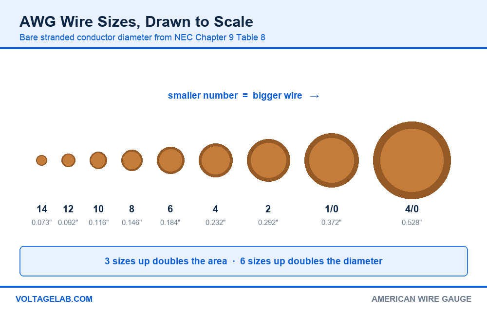
AWG started as a drawing count. To make thinner wire, a rod was pulled through a series of dies, and the gauge number roughly tracked how many dies it had passed through. More passes meant thinner wire, which is why the numbers run backwards: 14 AWG is smaller than 12, and 12 is smaller than 10.
Pass your electrical exam the first time
Practice real NEC exam questions with full code-referenced explanations and progress tracking — built for journeyman, master and apprentice exam prep.
Thousands of NEC practice questions with code-referenced answers
The steps are geometric, not linear. Each gauge is about 26% larger in area than the one before it. That gives two rules of thumb worth carrying in your head:
- Three gauge sizes doubles the area. 10 AWG has about twice the copper of 13 AWG, and 4 AWG about twice that of 7 AWG. Double the copper means roughly half the resistance.
- Six gauge sizes doubles the diameter. A 4 AWG conductor is about twice as thick as a 10 AWG one.
- Resistance follows area. Going up three sizes cuts voltage drop roughly in half on the same run.
Reading the numbers: AWG, aught and kcmil
Below 1 AWG the scale runs out of numbers, so it continues with zeros: 1/0, 2/0, 3/0 and 4/0, said aloud as one-aught through four-aught. 4/0 is the largest AWG size. Above it, conductors are named by area in kcmil (thousands of circular mils, sometimes written MCM on older drawings): 250, 300, 350, 500, 750 and up to 2000 kcmil in Table 310.16.
A circular mil is the area of a circle one mil (0.001 in) across. It is the unit used in the voltage drop formula and in Table 8, so it is worth knowing where it sits on the chart. Our breakdown of NEC Chapter 9 Table 8 covers the full conductor properties table, including solid and coated sizes.
Wire gauge size chart: diameter, area and resistance
| Size | Area (circular mils) | Area (mm²) | Strands | Diameter (in) | Copper Ω/1000 ft | Aluminum Ω/1000 ft |
|---|---|---|---|---|---|---|
| 14 AWG | 4,110 | 2.08 | 7 | 0.073 | 3.14 | 5.17 |
| 12 AWG | 6,530 | 3.31 | 7 | 0.092 | 1.98 | 3.25 |
| 10 AWG | 10,380 | 5.26 | 7 | 0.116 | 1.24 | 2.04 |
| 8 AWG | 16,510 | 8.37 | 7 | 0.146 | 0.778 | 1.28 |
| 6 AWG | 26,240 | 13.3 | 7 | 0.184 | 0.491 | 0.808 |
| 4 AWG | 41,740 | 21.2 | 7 | 0.232 | 0.308 | 0.508 |
| 3 AWG | 52,620 | 26.7 | 7 | 0.260 | 0.245 | 0.403 |
| 2 AWG | 66,360 | 33.6 | 7 | 0.292 | 0.194 | 0.319 |
| 1 AWG | 83,690 | 42.4 | 19 | 0.332 | 0.154 | 0.253 |
| 1/0 AWG | 105,600 | 53.5 | 19 | 0.372 | 0.122 | 0.201 |
| 2/0 AWG | 133,100 | 67.4 | 19 | 0.418 | 0.0967 | 0.159 |
| 3/0 AWG | 167,800 | 85.0 | 19 | 0.470 | 0.0766 | 0.126 |
| 4/0 AWG | 211,600 | 107 | 19 | 0.528 | 0.0608 | 0.100 |
| 250 kcmil | 250,000 | 127 | 37 | 0.575 | 0.0515 | 0.0847 |
| 300 kcmil | 300,000 | 152 | 37 | 0.630 | 0.0429 | 0.0707 |
| 350 kcmil | 350,000 | 177 | 37 | 0.681 | 0.0367 | 0.0605 |
| 500 kcmil | 500,000 | 253 | 37 | 0.813 | 0.0258 | 0.0424 |
For insulated dimensions, the numbers you need for conduit fill, use Chapter 9 Table 5 instead, because THHN, XHHW and RHW of the same gauge have very different outside diameters.
Wire gauge ampacity chart: NEC Table 310.16
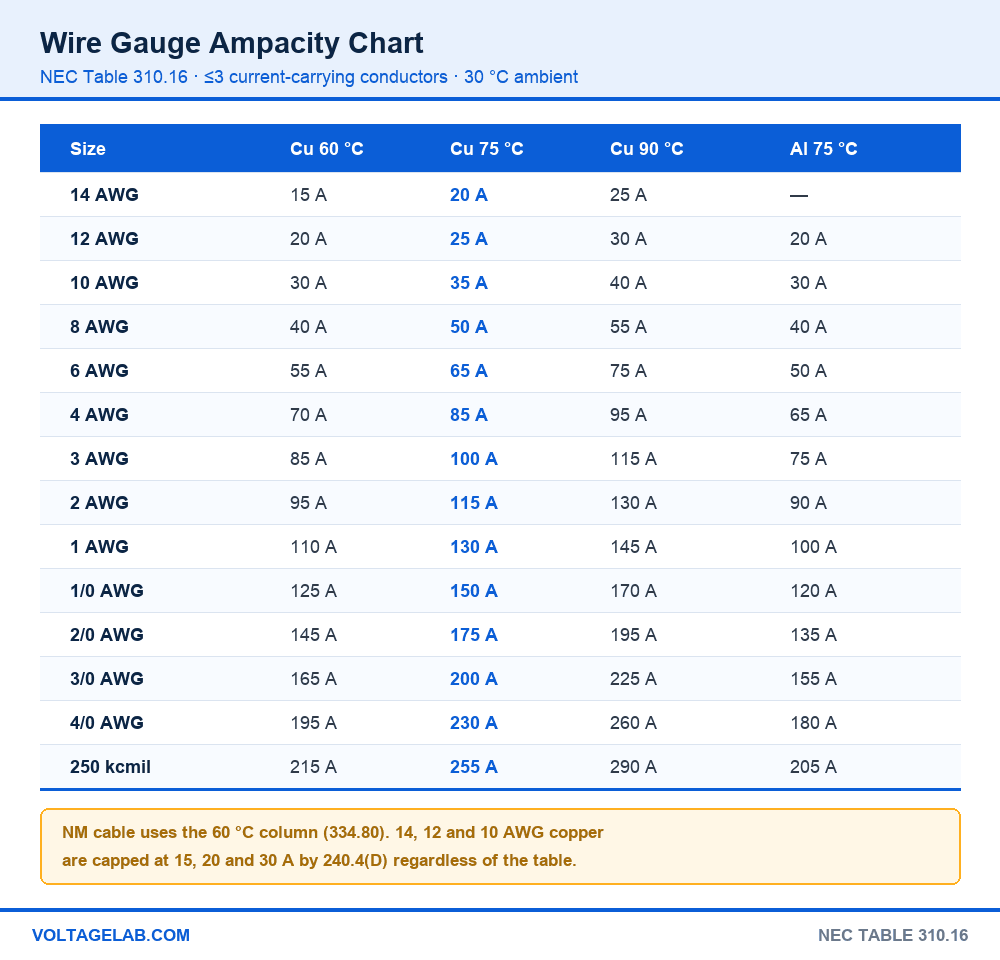
This is the part of the chart most people are looking for. NEC Table 310.16 lists ampacity for conductors rated up to 2000 volts, with no more than three current-carrying conductors in a raceway, cable or earth, at a 30 °C (86 °F) ambient. Each size has three columns, one for each insulation temperature rating.
| Size | Copper 60 °C | Copper 75 °C | Copper 90 °C | Aluminum 60 °C | Aluminum 75 °C | Aluminum 90 °C |
|---|---|---|---|---|---|---|
| 14 AWG | 15 A | 20 A | 25 A | — | — | — |
| 12 AWG | 20 A | 25 A | 30 A | 15 A | 20 A | 25 A |
| 10 AWG | 30 A | 35 A | 40 A | 25 A | 30 A | 35 A |
| 8 AWG | 40 A | 50 A | 55 A | 35 A | 40 A | 45 A |
| 6 AWG | 55 A | 65 A | 75 A | 40 A | 50 A | 55 A |
| 4 AWG | 70 A | 85 A | 95 A | 55 A | 65 A | 75 A |
| 3 AWG | 85 A | 100 A | 115 A | 65 A | 75 A | 85 A |
| 2 AWG | 95 A | 115 A | 130 A | 75 A | 90 A | 100 A |
| 1 AWG | 110 A | 130 A | 145 A | 85 A | 100 A | 115 A |
| 1/0 AWG | 125 A | 150 A | 170 A | 100 A | 120 A | 135 A |
| 2/0 AWG | 145 A | 175 A | 195 A | 115 A | 135 A | 150 A |
| 3/0 AWG | 165 A | 200 A | 225 A | 130 A | 155 A | 175 A |
| 4/0 AWG | 195 A | 230 A | 260 A | 150 A | 180 A | 205 A |
| 250 kcmil | 215 A | 255 A | 290 A | 170 A | 205 A | 230 A |
| 300 kcmil | 240 A | 285 A | 320 A | 195 A | 230 A | 260 A |
| 350 kcmil | 260 A | 310 A | 350 A | 210 A | 250 A | 280 A |
| 400 kcmil | 280 A | 335 A | 380 A | 225 A | 270 A | 305 A |
| 500 kcmil | 320 A | 380 A | 430 A | 260 A | 310 A | 350 A |
The columns are not a menu. The 60 °C column covers TW, UF and NM cable. The 75 °C column covers THW, THWN, XHHW and USE, and it is where most breaker and lug ratings sit. The 90 °C column covers THHN, THWN-2 and XHHW-2, but it is mostly a starting point for derating. For a walk through every column and footnote, see how to read NEC Table 310.16, and for one size in depth, our 8 AWG wire ampacity breakdown.
The Romex trap: NM-B cable has 90 °C conductors inside it, but NEC 334.80 limits its ampacity to the 60 °C column. So 8 AWG NM is a 40-amp cable, not 50, and 6 AWG NM is 55 A. Putting 8/2 or 8/3 Romex on a 50-amp range or EV breaker is one of the most common failed rough-ins in residential work. The 90 °C rating may only be used as the starting point for derating.
UF cable carries the same 60 °C restriction under 340.80. If you need the 75 °C ampacity, run individual THWN-2 conductors in conduit, or use a cable type whose listing and terminations support it.
Wire size by amperage: choosing the right gauge
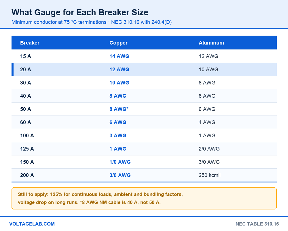
Most of the time you start from the breaker, not the wire. The table below gives the smallest conductor that works at 75 °C terminations under the standard Table 310.16 conditions. Treat it as the floor, not the final answer.
| Breaker | Copper (75 °C) | Aluminum (75 °C) | Typical circuit |
|---|---|---|---|
| 15 A | 14 AWG | 12 AWG | Lighting, general receptacles |
| 20 A | 12 AWG | 10 AWG | Kitchen, bath and laundry receptacles |
| 30 A | 10 AWG | 8 AWG | Dryer, water heater, small A/C |
| 40 A | 8 AWG | 8 AWG | Cooktop, 32 A EV charger |
| 50 A | 8 AWG* | 6 AWG | Range, welder, 40 A EV charger |
| 60 A | 6 AWG | 4 AWG | Subpanel, tankless heater, 48 A EV charger |
| 100 A | 3 AWG | 1 AWG | Subpanel or feeder |
| 125 A | 1 AWG | 2/0 AWG | Feeder |
| 150 A | 1/0 AWG | 3/0 AWG | Feeder |
| 200 A | 3/0 AWG | 250 kcmil | Feeder (dwelling services can use 310.12) |
A five-step method for picking the gauge
Step 1: find the load. Use the nameplate or the calculated load. For a continuous load, which runs three hours or more such as an EV charger or water heater, multiply by 125% per 210.19(A)(1) and 215.2(A)(1). A 40-amp EV charger therefore needs a 50-amp circuit.
Step 2: pick the column. Check the breaker and equipment lugs. Under 110.14(C), circuits of 100 A or less default to the 60 °C column unless the terminations are marked 75 °C. Most modern breakers are marked 60/75 °C. NM cable is always 60 °C.
Step 3: correct for heat and bundling. If the ambient is above 30 °C, or more than three current-carrying conductors share a raceway or are bundled, apply the factors in 310.15(B) and 310.15(C)(1). Start from the 90 °C value if the insulation allows. Our guide to conductor adjustment factors has the full percentages, and the conductor derating calculator does the arithmetic.
Study smarter with VoltageLab
Built for electricians, apprentices, and electrical engineers who want faster practice and better exam prep.
⭐️ Join thousands of electricians upgrading their skills
Step 4: check the small-conductor caps. Apply 240.4(D) to 14, 12 and 10 AWG copper and to 12 and 10 AWG aluminum.
Step 5: check voltage drop. On long runs, the gauge that passes ampacity may still lose too much voltage. Size up until the drop is acceptable, as covered in the next section.
The one that catches everyone: 12 AWG copper shows 25 A at 75 °C and 30 A at 90 °C, so it looks like it can take a 25 or 30-amp breaker. It cannot. NEC 240.4(D) limits the overcurrent device to 15 A on 14 AWG, 20 A on 12 AWG and 30 A on 10 AWG copper, and 15 A and 25 A on 12 and 10 AWG aluminum. The higher table values exist only to give you headroom when derating.
When the chart size is enough, and when to go bigger
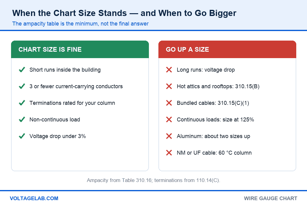
The ampacity table answers one question: how much current the insulation can carry without overheating. It says nothing about how far the current travels or what the wire passes through on the way. These are the cases where the first answer from the chart stands, and where it does not.
The chart size usually stands
- Short branch circuits inside a conditioned building
- No more than three current-carrying conductors in the raceway or cable
- Terminations marked for the column you used
- Non-continuous loads at or under the breaker rating
- Runs short enough that voltage drop stays under about 3%
Go up a size, or more
- Long runs to a detached garage, well pump or outbuilding, where voltage drop takes over
- Raceways or cables in hot attics or on rooftops, where 310.15(B) correction applies
- More than three current-carrying conductors bundled together, under 310.15(C)(1)
- Continuous loads, which must be sized at 125%
- Aluminum instead of copper, which needs about two sizes larger
- NM or UF cable, which is limited to the 60 °C column
- Motor circuits, which are sized from 430.22 and the full-load current tables, not the nameplate
Voltage drop: the reason long runs need thicker wire
For single-phase circuits, voltage drop is VD = 2 × K × I × L ÷ CM, where K is 12.9 for copper, I is the load in amps, L is the one-way length in feet, and CM is the circular mil area from the chart above. A 20-amp load 100 feet away on 12 AWG drops 7.9 V, which is 6.6% of 120 V. Moving to 10 AWG cuts that to 5.0 V (4.1%), and 8 AWG to 3.1 V (2.6%).
The informational notes in NEC 210.19 and 215.2 recommend a maximum of 3% on a branch circuit and 5% combined with the feeder. They are recommendations, not requirements, but motors, LED drivers and EV chargers all behave better within it. Our voltage drop guide has three-phase examples, and the voltage drop calculator gives the answer for any gauge and length.
Copper vs aluminum wire gauge
| Factor | Copper | Aluminum |
|---|---|---|
| Ampacity at the same gauge | Higher | Lower, about one to two sizes behind |
| Smallest size in Table 310.16 | 14 AWG for building wire | 12 AWG, and 240.4(D) caps it at 15 A |
| Resistance (2/0 example) | 0.0967 Ω per 1000 ft | 0.159 Ω per 1000 ft |
| Equivalent for a 200 A feeder (75 °C) | 3/0 AWG | 250 kcmil |
| Dwelling 200 A service (310.12) | 2/0 AWG | 4/0 AWG |
| Termination | Any listed lug | Lugs marked AL or AL7CU/AL9CU, with antioxidant where the manufacturer requires it |
| Typical use | Branch circuits, all sizes | Feeders and services, 6 AWG and larger |
| Cost and weight | Higher | Much lower, the main reason it is used |
Modern AA-8000 series aluminum building wire is not the 1960s branch-circuit aluminum that gave the material its reputation. In feeder sizes it is standard practice. The 310.12 dwelling service table allows a smaller conductor than Table 310.16 for a whole-house service, and our guides to 100-amp service wire size and 400-amp service wire size work through both metals. For a subpanel feeder, see 60-amp subpanel wire size, and to size the ground that runs with it, NEC 250.122 equipment grounding conductors.
Should you switch to aluminum for a feeder?
Pros
- Roughly a third of the cost of copper at feeder sizes
- Much lighter, which makes long pulls and overhead runs easier
- Fully recognised in Table 310.16 and the 310.12 dwelling table
- Standard for service-entrance cable and utility drops, so inspectors expect it
Cons
- Needs about two gauge sizes larger for the same ampacity
- Larger conductors mean larger conduit, so check fill again
- Every lug must be listed for aluminum and torqued to its marked value
- Not practical for 15 and 20-amp branch circuits
Working with wire gauge in the field
Do
- Read the size and insulation off the jacket before you land it
- Check the breaker and lug temperature marking before using the 75 °C column
- Size continuous loads at 125% before you open the chart
- Run the voltage drop numbers on anything over about 100 feet
- Torque every termination to the marked value per 110.14(D)
Avoid
- Sizing a breaker off the 90 °C column
- Putting 8 AWG NM cable on a 50-amp breaker
- Swapping aluminum for copper at the same gauge
- Ignoring bundling when several cables share a bored hole or a raceway
- Trusting a chart that does not name its column and conditions
Frequently asked questions
What size wire do I need for a 30-amp breaker?
10 AWG copper. NEC 240.4(D) allows 10 AWG copper on a breaker up to 30 A, and it is the standard size for dryers and water heaters. In aluminum you need 8 AWG, because 10 AWG aluminum is capped at 25 A.
Is 12 gauge wire good for 20 amps?
Yes. 12 AWG copper is the standard conductor for a 20-amp circuit, and 240.4(D) sets 20 A as its maximum overcurrent protection. On a long run, check voltage drop: past about 70 to 80 feet at full load, 10 AWG is often the better choice.
What gauge wire for 50 amps?
6 AWG copper in NM cable, or 8 AWG copper as individual THHN/THWN-2 conductors with 75 °C terminations. In aluminum, 6 AWG at 75 °C. The cable type decides the answer, because NM is limited to the 60 °C column.
Is a bigger gauge number a bigger wire?
No, the opposite. In the AWG system, the higher the number, the thinner the wire. 14 AWG is smaller than 12 AWG, and 4/0 is the largest AWG size before the scale switches to kcmil.
What is the difference between AWG and kcmil?
AWG is a numbered gauge scale that ends at 4/0. Above that, conductors are named by cross-sectional area in kcmil, thousands of circular mils. 250 kcmil is the next standard size above 4/0, which is about 212 kcmil.
What wire size for a 100-amp subpanel?
3 AWG copper or 1 AWG aluminum at 75 °C under Table 310.16. The smaller sizes in 310.12 apply only to a dwelling’s main service or main feeder carrying the whole load, not to a subpanel.
Can I use the 90 °C column for ampacity?
Only as the starting point for derating, when the conductor insulation is rated 90 °C. The final ampacity is limited by the termination rating under 110.14(C), which is 60 or 75 °C for nearly all breakers and equipment.
Why does my chart show different amps than another chart?
Most online charts pick one column and do not say which. One chart showing 8 AWG at 40 A and another at 55 A are both reading Table 310.16, at 60 °C and 90 °C respectively. A trustworthy chart names its column, its metal and its conditions.
The bottom line
A wire gauge chart is two tables working together. Chapter 9 Table 8 tells you how much metal is in the wire, and Table 310.16 tells you how much current that metal may carry. Smaller numbers mean bigger wire, three sizes doubles the area, and copper at 75 °C runs 15, 20, 30, 50, 65 and 85 amps from 14 AWG to 4 AWG.
Two habits keep you out of trouble. Read the right column, which means 60 °C for NM cable and the termination rating for everything else. And treat the chart’s answer as the minimum, then let continuous load, heat, bundling and distance move you up from it. To check a real circuit, run it through the free NEC wire size calculator, or go deeper on the table itself with our NEC 310.16 ampacity chart guide.
FREE PRACTICE TOOL
Think you'd pass this on a real exam?
Test what you just read with instant-feedback quizzes built around real code questions — not generic trivia.
5
Code standards
10,000+
Active learners
100%
Free to start
Instant explanations on every answer, right or wrong
NEC, BS7671, AS/NZS, CEC, and DIN VDE covered
Bite-sized quizzes you can finish in 5 minutes
No signup required to try your first quiz
No account needed · Takes less than 2 minutes