


You show up to open a pad-mounted transformer cabinet and there is no padlock on it — just a brass key sticking out of a small steel block bolted to the door, and an identical block on the load-break switch a few feet away. You cannot pull the key out of the switch until the switch is open. You cannot open the door until that key goes into the door lock. The order of operations has been decided for you, by steel, before you arrived.
That is a Kirk key interlock, and it is one of the few pieces of safety hardware on a job site that works whether or not anyone is paying attention. It also gets misunderstood constantly — crews treat a trapped key as if it were a lockout device, engineers specify a scheme without documenting it, and a single duplicate key cut at a hardware store quietly defeats a system that cost five figures.
Study smarter with VoltageLab
Built for electricians, apprentices, and electrical engineers who want faster practice and better exam prep.
⭐️ Join thousands of electricians upgrading their skills
This guide covers what a Kirk key interlock is and how the mechanism works, the common interlock schemes and what each one prevents, where the NEC and NFPA 70E actually touch the subject, and the hard line between sequence control and an electrically safe work condition.
Quick Answer
A Kirk key interlock is a mechanical trapped-key device that forces a fixed order of operations between two or more pieces of equipment. A uniquely cut key is held captive in a lock until that device reaches a defined position — usually open — and only then is the key released to unlock the next device. Because one key can only be in one lock at a time, the wrong combination of positions becomes physically impossible.
“Kirk” is a brand name that became the generic term, the way people say Romex. No NEC article requires a Kirk key by name. It gets installed because the equipment listing, the utility, or the engineer’s sequence-of-operation calls for it — most often to stop two sources being paralleled, to block access to an energised compartment, or to prevent racking a closed breaker. It is not lockout/tagout and does not establish an electrically safe work condition.
Key Takeaways
- A trapped-key interlock releases its key only when the device it controls is in the safe position, so the sequence is enforced mechanically rather than by procedure
- Kirk is one brand among several — Castell, Bourré and Trayvou trapped-key systems work on the same principle
- The classic applications are main-tie-main switchgear, loop-feed pad-mounted transformers, medium-voltage compartment access, breaker racking and generator-versus-utility transfer
- NFPA 70E does not accept an interlock as lockout/tagout — only a disconnecting means can be locked out, and absence of voltage still has to be verified
- NEC 495.46 requires circuit breakers over 1000 volts to be lockable in the open position, and drawout mechanisms to be lockable out of the connected position
- Articles 700, 701 and 702 call for transfer equipment on standby systems; a key interlock is not a general substitute for a transfer switch
- Key control is the weak point of every scheme — duplicate keys, spare keys left in a drawer and undocumented changes are how interlocks get defeated
What a Kirk key interlock actually is
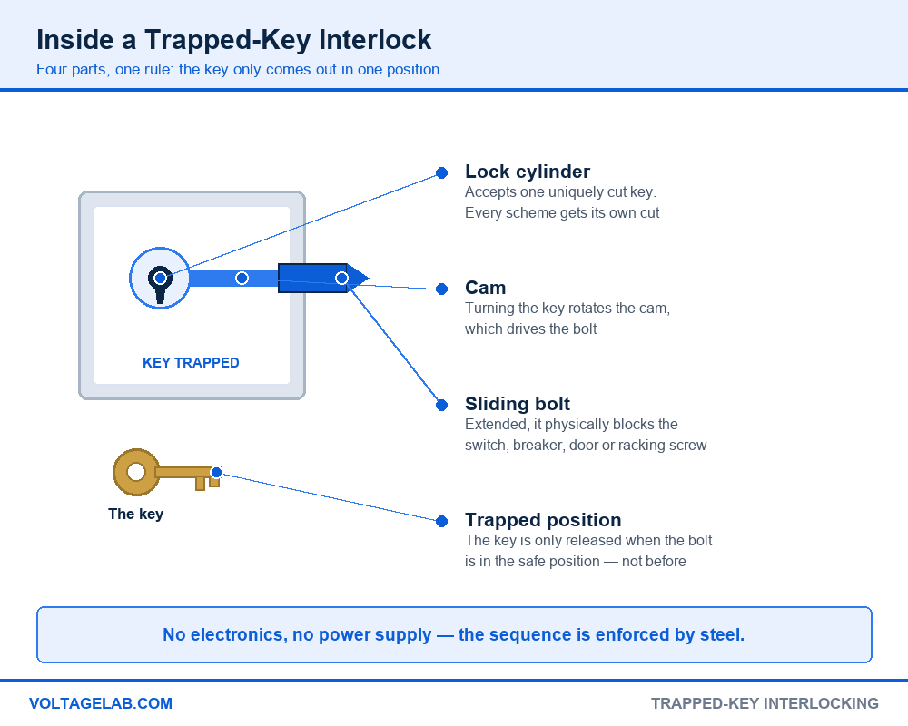
Strip the branding away and the device is simple. A lock cylinder accepts one uniquely cut key. Turning that key rotates a cam, and the cam drives a sliding bolt in or out of the housing. When the bolt is extended it sits in the path of something — a switch operating handle, a breaker’s trip bar, a cabinet door, a racking screw — and that thing cannot move.
Pass your electrical exam the first time
Practice real NEC exam questions with full code-referenced explanations and progress tracking — built for journeyman, master and apprentice exam prep.
Thousands of NEC practice questions with code-referenced answers
The safety comes from one design decision: the key can only be withdrawn in one of the two positions. In the other position it is trapped. So a key sitting in your hand is proof that the device it came from is in the safe position, and it stays proof for as long as you hold it. That is a far stronger guarantee than a sign, a procedure, or a colleague’s word.
- The key. Cut to a code unique to that scheme, stamped with an identifier. Keys from one job do not fit another.
- The lock unit. Cylinder, cam and bolt in a housing shaped for the equipment it mounts to — bolt-on for a switch, flush for a panel, or built into the breaker by the manufacturer.
- Key exchange blocks. Where a scheme needs several keys surrendered before one is released, an exchange block does the arithmetic. Put two keys in, take one out.
- Solenoid and time-delay units. Optional additions that hold a key until a circuit is proven dead or a machine has coasted to a stop.
Where the name comes from
Trapped-key interlocking goes back to railway signalling in the 1890s, where it was used to stop a signal being cleared while points were set wrong. The idea moved into power generation and switchgear in the early twentieth century, and several names attached to it — Castell in Britain, Bourré and Trayvou in France, Kirk in the United States.
The Kirk Key Interlock Company has manufactured them in the US since the early 1900s and, per the manufacturer, has been based in Ohio since 1999 under a series of owners. In American practice the brand name won, and any trapped-key device tends to get called a Kirk key regardless of who made it. Specify by function, not by brand, and check that the parts on site match the scheme drawing.
Key interlock vs breaker interlock vs transfer switch vs LOTO
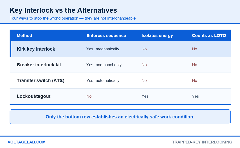
These four get used interchangeably in conversation and they do not do the same job:
| Method | Enforces a sequence | Isolates energy | Establishes an ESWC |
|---|---|---|---|
| Kirk key interlock | Yes, mechanically, across separate enclosures | No | No |
| Breaker interlock kit | Yes, but only within one panel | No | No |
| Transfer switch | Yes, and it operates the transfer itself | No | No |
| Lockout/tagout | No — it holds one state | Yes | Yes, with voltage verification |
The row that matters is the last one. A key interlock tells you the switch is open; lockout/tagout is what keeps it open while your hands are inside, and a voltage test is what proves it. Our guide to why lockout/tagout matters for electricians walks through the full sequence.
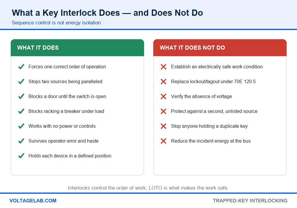
The mistake that gets people hurt: treating a trapped key as a personal lockout device. Holding the key proves the switch is open — it does not prove the equipment is dead, it does not stop a second source, and it is not your lock on the disconnecting means. NFPA 70E requires the electrically safe work condition to be established at the disconnecting means and verified by testing for absence of voltage. Put your own lock on, test, and keep the key as what it is: evidence about one device’s position.
NFPA 70E also asks the other direction of the same question during lockout planning: review the drawings and confirm that no interlock operation anywhere in the system can re-energise the circuit you are working on. An interlock scheme is part of the system you have to understand before you lock out, not a shortcut past it. The 2026 NFPA 70E updates are worth reading alongside this.
Common interlock schemes and what each one prevents
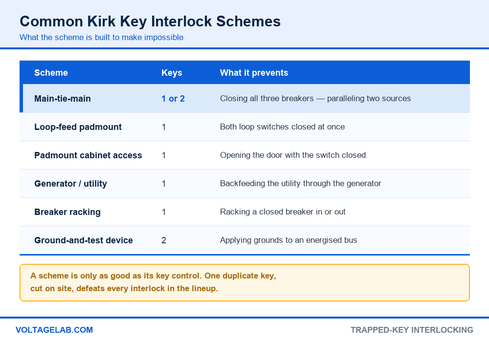
Almost every scheme you will meet in the field is one of six patterns, or a combination of them:
| Scheme | Typical keys | What it makes impossible | Where you see it |
|---|---|---|---|
| Main-tie-main | 1 or 2 | All three breakers closed at once, paralleling two sources | Dual-utility switchboards, data centres, hospitals |
| Loop-feed switching | 1 | Both loop switches closed, back-feeding the loop | Pad-mounted transformers on a utility loop |
| Compartment access | 1 | Opening a door or cover with the supply switch closed | Pad-mount cabinets, MV terminations, kilns, test cells |
| Generator / utility | 1 | Closing the generator breaker with the utility breaker closed | Standby generators without an ATS |
| Breaker racking | 1 | Racking a closed breaker into or out of the cell | Drawout switchgear |
| Ground-and-test | 2 | Applying grounds to a bus that has not been isolated | MV switchgear maintenance |
How to read or verify a scheme in five steps
Step 1 — get the sequence-of-operation drawing. Every interlock scheme has one, or should. It lists each lock, each key, each key’s cut code, and the order in which they move. Without it you are reverse-engineering a safety system by trial and error on live gear.
Step 2 — count the keys and count the locks. A scheme’s whole logic is that there are fewer keys than locks. If the drawing says one key and you find two identical keys on site, the interlock is defeated and the scheme is no longer doing anything.
Step 3 — identify the impossible state. Ask what combination of positions the design is meant to prevent, then confirm the keys physically cannot allow it. For main-tie-main, that state is all three breakers closed. For a loop feed, it is both switches closed.
Step 4 — check the key cut codes against the stamps. Locks and keys carry stamped identifiers. Match them to the drawing. A replacement lock ordered by cylinder size rather than by cut code is a common and quiet failure.
Study smarter with VoltageLab
Built for electricians, apprentices, and electrical engineers who want faster practice and better exam prep.
⭐️ Join thousands of electricians upgrading their skills
Step 5 — exercise the sequence de-energised. Before the system is put into service, walk the whole sequence with the gear dead and confirm each key releases only where it should. Document it, and note where the spare keys live and who controls them.
The one that catches everyone: spare keys. An interlock scheme is a physical argument that depends entirely on there being exactly as many keys as the design says. One spare in a maintenance drawer, one duplicate cut because somebody lost theirs, and the argument collapses without anything looking different. Spares belong under documented control — not in the panel, not on the shop key board, and never on the same ring as the key they duplicate.
Where key interlocks are required — and where they are not enough
There is no NEC article headed “Kirk key interlock.” What the Code does is require certain outcomes, and a key interlock is one accepted way of achieving some of them.
Where you will find them required or expected
- Medium-voltage switchgear. NEC 495.46 — Article 490 in editions before 2023 — requires circuit breakers over 1000 volts to be capable of being locked in the open position, and drawout mechanisms to be lockable so they cannot be moved to the connected position, with the locking provision meeting 110.25. Manufacturers commonly deliver that with integral key interlocks.
- Utility-owned pad-mounted equipment. Most utilities require a key interlock between the load-break switch and the transformer cabinet before they will energise. This is a utility specification, not an NEC rule, so get it in writing early.
- Dual-source and main-tie-main designs. Where two supplies must never be paralleled, the interlock is the engineered control that makes it impossible, and the sequence appears on the one-line.
- Equipment listings. Kilns, test cells, capacitor banks, high-voltage laboratory gear and much industrial machinery are listed with an access interlock as part of the product. Removing it voids the listing.
- Standby generators without automatic transfer. Where the design uses two breakers instead of a transfer switch, a mechanical interlock is what stops the two from closing together.
Where an interlock is not the answer
- As a substitute for lockout/tagout before working on equipment
- As proof of de-energisation — absence of voltage still has to be tested
- As protection against a source the scheme does not know about, such as a second feed, stored energy or a PV inverter
- As a replacement for required transfer equipment on an emergency or legally required standby system
- As a way to reduce incident energy — the arc flash study does not care that a key exists
The generator question
This is where most arguments with an AHJ start. For emergency systems, NEC 700.5 requires transfer equipment that is automatic, identified for emergency use and approved — a pair of interlocked breakers is not that. Articles 701 and 702 carry parallel requirements for legally required and optional standby systems, and 702.5 requires transfer equipment designed and installed to prevent inadvertent interconnection of the sources.
The narrow opening is the exception in 702.5, which permits temporary connection of a portable generator without transfer equipment where conditions of maintenance and supervision ensure only qualified persons service the installation and the normal supply is physically isolated by a lockable disconnecting means or by disconnecting the normal supply conductors. That is a temporary, supervised arrangement — not a licence to build a permanent generator inlet on a mechanical interlock. Listed breaker interlock kits are widely accepted for optional standby on dwellings, but the acceptance comes from the AHJ and the kit’s listing, so ask before you buy. For the alternative, see our walkthroughs of transfer switch installation and operation and three-phase ATS connection.
Kirk key interlocks vs the other ways to enforce a sequence
| Consideration | Trapped key | Mechanical linkage | Electrical interlock | Administrative |
|---|---|---|---|---|
| Works across separate enclosures | Yes | No | Yes | Yes |
| Works with control power lost | Yes | Yes | No | N/A |
| Defeatable without tools | Only with a spare key | No | By jumpering | Yes, easily |
| Retrofits to existing gear | Usually | Rarely | Sometimes | Yes |
| Survives operator error | Yes | Yes | Usually | No |
Interlocks sit inside a wider safety picture. The equipment they guard still needs correct NEC and NFPA signage, proper 110.26 working space, and a grounding scheme that holds up under fault — see NEC Article 250 and, for systems where earth-fault current is deliberately limited, high-resistance grounding. The habits that keep people alive around this gear are covered in preventing electrical shocks on the job site.
Is a key interlock the right control for your design?
Pros
- Purely mechanical — no control power, no wiring, nothing to fail silently
- Works between devices in different enclosures, rooms or buildings
- Retrofits to most existing switchgear and pad-mount equipment
- Enforces the sequence regardless of training, haste or shift change
- Cheap relative to the switchgear damage a paralleling event causes
Cons
- Entirely dependent on key control, which is an administrative problem again
- Easy to misread as a lockout device, with serious consequences
- Undocumented schemes become unmaintainable once the designer leaves
- Adds manual steps, so transfers take minutes rather than milliseconds
Working with key interlocks in the field
Do
- Find and read the sequence-of-operation drawing before you touch a key
- Apply your own lock and test for absence of voltage after the sequence, every time
- Match stamped key and lock codes against the drawing during commissioning
- Exercise the whole sequence de-energised before the system goes live
- Keep spare keys under documented control, away from the equipment
Avoid
- Treating a trapped key as your personal lockout device
- Cutting a duplicate key because the original went missing
- Forcing a bolt, shimming a lock or drilling a cover to get past a scheme
- Replacing a lock by physical size instead of by cut code
- Adding a breaker or source to a lineup without revising the interlock scheme
Frequently asked questions
What is a Kirk key interlock?
A mechanical trapped-key interlock that releases its key only when the device it controls reaches a defined position. Because the same key is needed to unlock the next device, the system forces one correct order of operations and makes the unsafe combination physically impossible.
Is a Kirk key interlock required by the NEC?
Not by name. The NEC requires outcomes — for example, 495.46 requires breakers over 1000 volts to be lockable open and drawout mechanisms lockable out of the connected position — and a key interlock is one accepted way to deliver them. Most installations happen because of the equipment listing, the utility’s specification, or the engineer’s design.
Can a Kirk key replace lockout/tagout?
No. NFPA 70E requires locks and tags on the disconnecting means and verification of the absence of voltage before work begins. A trapped key tells you one device’s position; it does not isolate energy, does not prove the circuit is dead, and is not your personal lock.
Can I use a key interlock instead of a transfer switch?
Generally no for emergency and legally required standby systems, where Articles 700 and 701 call for transfer equipment identified for the purpose. Article 702 contains a narrow exception for temporary portable generator connections under qualified supervision with the normal supply isolated by a lockable disconnect. Anything permanent should be confirmed with the AHJ first.
Why is it called a Kirk key?
Kirk is a manufacturer of trapped-key interlocks that has been building them in the United States since the early 1900s. The brand name became the generic term in American practice, the same way Romex stands in for NM cable. Castell, Bourré and Trayvou are other names on the same technology.
What happens if a key interlock key is lost?
Go to the manufacturer with the stamped cut code and the scheme documentation, and treat the loss as a reportable event. Do not cut a duplicate locally — an uncontrolled key silently defeats the whole scheme, and nothing on the equipment will look any different afterwards.
Do key interlocks work on low-voltage equipment?
Yes. They are most associated with medium-voltage switchgear, but they are widely used on 480 V main-tie-main switchboards, generator paralleling breakers, capacitor banks and machine guarding, where the same sequencing problem exists.
Who is responsible for the interlock scheme documentation?
The designer produces the sequence of operation, the manufacturer supplies the key chart and cut codes, and the owner maintains both for the life of the equipment. In practice the documentation is the first thing lost, so photograph the key chart at commissioning and keep it with the one-line diagram.
The bottom line
A Kirk key interlock earns its place because it removes a decision from a person and hands it to a piece of steel. No control power, no software, no dependence on whether the operator read the procedure — the wrong sequence simply will not go. For paralleling prevention, compartment access and racking control, nothing else is that robust for the money.
The two restraints are both about discipline rather than hardware. Keep the key count honest, because a single uncontrolled duplicate turns the whole scheme into decoration. And never let a trapped key stand in for lockout/tagout — hold the key, then put your own lock on and test for absence of voltage. For the wider safety picture around this equipment, start with our guide to lockout/tagout for electricians.
FREE PRACTICE TOOL
Think you'd pass this on a real exam?
Test what you just read with instant-feedback quizzes built around real code questions — not generic trivia.
5
Code standards
10,000+
Active learners
100%
Free to start
Instant explanations on every answer, right or wrong
NEC, BS7671, AS/NZS, CEC, and DIN VDE covered
Bite-sized quizzes you can finish in 5 minutes
No signup required to try your first quiz
No account needed · Takes less than 2 minutes