


Walk into the electrical room of a paper mill or a plating shop and you will see something no commercial building has: a small enclosure next to the substation with a resistor grid inside, a voltmeter on the door, and an alarm horn that has clearly been silenced more than once. The 480-volt system feeding that plant has a ground fault on it right now, and every machine in the building is still running. That is high resistance grounding doing exactly what it was installed to do.
It catches people out because it inverts the rule every electrician learns first. On a solidly grounded system a phase-to-ground fault is a dead short and the breaker clears it in cycles. Here the same fault draws about five amps, nothing trips, and the only evidence is a lamp on a panel. Miss it, let a second ground fault land on a different phase, and you have a phase-to-phase fault through two pieces of conduit with nothing watching it.
Study smarter with VoltageLab
Built for electricians, apprentices, and electrical engineers who want faster practice and better exam prep.
⭐️ Join thousands of electricians upgrading their skills
This guide covers what high resistance grounding is, how the neutral grounding resistor is sized, how HRG compares with solidly grounded, low-resistance and ungrounded systems, and what NEC 250.36 and 250.187 require before you may use it.
Quick Answer
High resistance grounding (HRG) connects the system neutral point to the grounding electrode conductor through a resistor instead of a solid bonding jumper. The resistor limits a phase-to-ground fault to roughly 5 to 10 amps — enough current for a relay to detect the fault and alarm, but far too little to trip a breaker, arc-blast an enclosure, or burn a hole in a motor stator. The plant keeps running while maintenance walks the feeders and finds the fault.
You do not get to choose it freely. NEC 250.36 permits it on 3-phase systems from 480 V to 1000 V only where qualified persons service the installation, ground detectors are installed, and line-to-neutral loads are not served. That last condition is the one that rules out most buildings: if you are running 277-volt lighting off the system, high resistance grounding is off the table.
Key Takeaways
- High resistance grounding inserts a neutral grounding resistor between the system neutral point and ground, limiting ground-fault current to roughly 5–10 amps
- A first ground fault on an HRG system does not trip anything — it alarms, and the process keeps running while the fault is located
- NEC 250.36 permits impedance grounding on 480 V to 1000 V systems only if qualified persons service it, ground detectors are installed, and no line-to-neutral loads are served
- Systems over 1000 volts fall under NEC 250.187, which imposes the same three conditions
- The resistor must let through more current than the system’s total capacitive charging current, or arcing ground faults can drive damaging transient overvoltages
- During a ground fault the two unfaulted phases sit at full line-to-line voltage above ground, so every conductor and every surge arrester on the system must be rated for it
- A neutral grounding resistor that fails open turns the installation into an ungrounded system with no warning, which is why NGR monitoring is standard practice
What high resistance grounding actually is
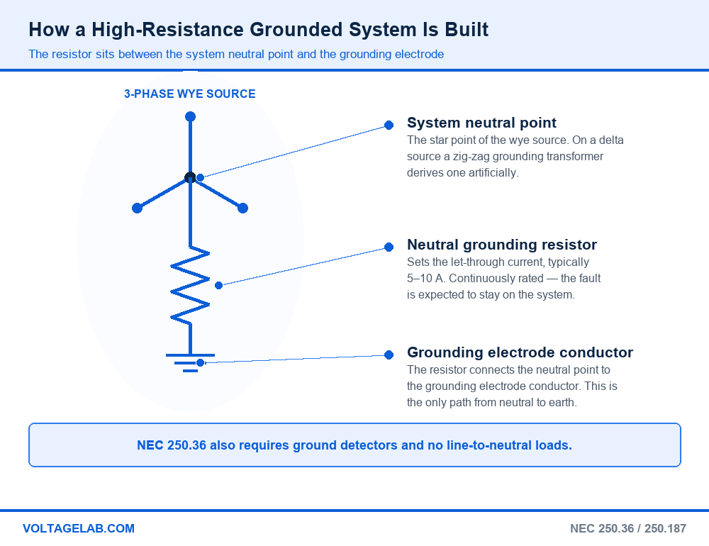
Every three-phase wye system has a neutral point at the transformer or generator, and what you connect that point to is the whole question of system grounding. Bolt it to the grounding electrode system and you have a solidly grounded system. Leave it floating and you have an ungrounded system. Put a resistor in between and you have a resistance-grounded system — high or low, depending on how much current that resistor allows.
Pass your electrical exam the first time
Practice real NEC exam questions with full code-referenced explanations and progress tracking — built for journeyman, master and apprentice exam prep.
Thousands of NEC practice questions with code-referenced answers
High resistance grounding sits at the top of that range: the resistor is sized so a bolted phase-to-ground fault draws only a few amps. That one choice changes everything downstream. No overcurrent device sees anything, almost no energy reaches the fault point, and because the neutral is still tied to ground through a defined resistance, the system voltage stays referenced to earth instead of floating on its own capacitance.
The five parts of an HRG system
- The neutral grounding resistor (NGR). A stainless steel or nichrome resistor grid in a ventilated enclosure. It sets the let-through current and defines the system.
- The grounding impedance conductor. Runs from the neutral point to the resistor and on to the grounding electrode conductor. NEC 250.36 requires this path to be insulated and sized against the resistor’s rating.
- A grounding transformer, when there is no neutral. Delta sources have no neutral point to grab, so a zig-zag grounding transformer derives one and the NGR connects to that.
- Ground detection and alarm. Three voltmeters or a ground-fault relay watching neutral-to-ground voltage. NEC 250.36 makes detectors mandatory, not optional.
- A pulsing circuit for fault location. Most modern NGR panels switch part of the resistance in and out about once a second, so the fault current pulses and a technician can follow it feeder by feeder with a clamp-on ammeter.
If you have never seen a system where the neutral point is deliberately not bonded to the enclosure, review how separately derived systems are grounded and bonded first — HRG is that same connection with a resistor spliced into it.
High resistance grounding vs solidly grounded, low-resistance and ungrounded
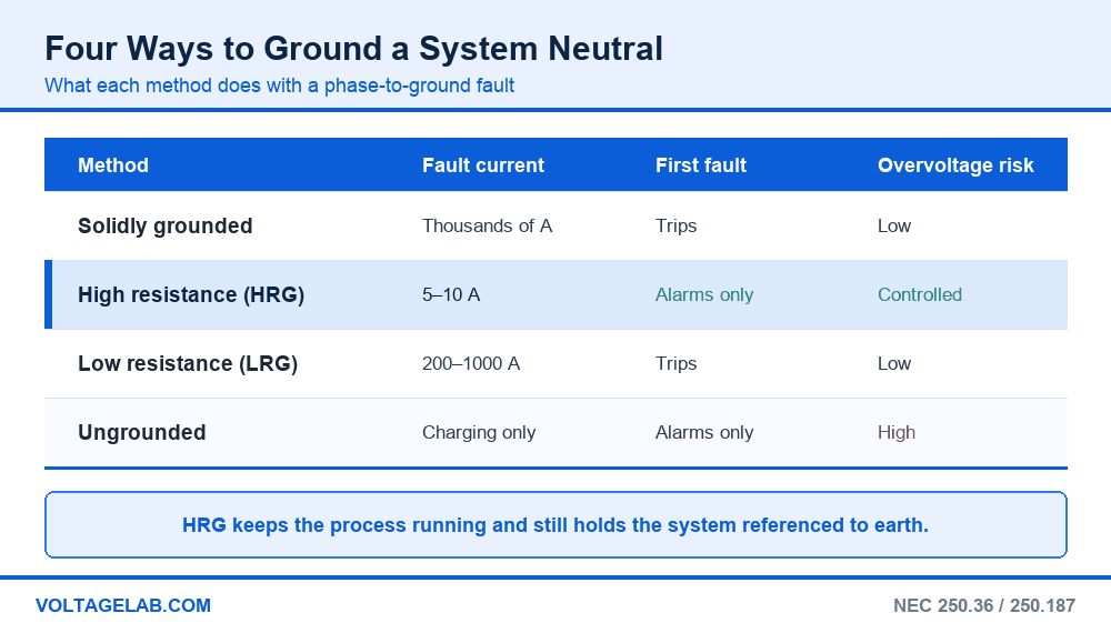
There are four ways to treat a system neutral, and each trades one risk against another. Fault damage, continuity of service and transient overvoltage do not all improve together.
| Characteristic | Solidly grounded | High resistance | Low resistance | Ungrounded |
|---|---|---|---|---|
| Ground-fault current | Thousands of amps | About 5–10 A | 200–1000 A typical | Charging current only |
| First ground fault | Trips | Alarms only | Trips | Alarms only |
| Transient overvoltage risk | Low | Controlled | Low | High |
| Line-to-neutral loads | Yes | Not permitted | Not permitted | No neutral |
| Arc-flash energy, L-G fault | Full | Near zero | Reduced | Near zero |
The row that decides most projects is the fourth one. HRG is only legal where the system serves no line-to-neutral loads, and a 480Y/277 V system feeding 277-volt lighting is a line-to-neutral load. That is why HRG shows up in process plants with 480-volt motor loads and separate lighting transformers, and almost never in an office building.
Code trap: You cannot land a single 277-volt lighting circuit, control transformer or receptacle on the neutral of a high-resistance grounded system. NEC 250.36 lists “line-to-neutral loads are not served” as a condition of using impedance grounding at all — not a design preference. The load would sit in series with the resistor, so it would never see full voltage, and during a ground fault on another phase it would be driven to line-to-line potential. Derive 120/208 V and 277 V loads from a separate, solidly grounded transformer.
Sizing the neutral grounding resistor
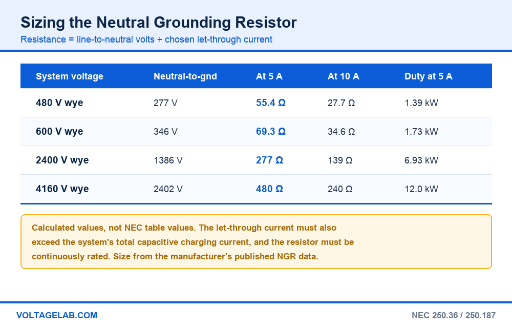
The resistor sees the system’s line-to-neutral voltage across it when a phase goes solidly to ground, which makes the arithmetic simple: divide that voltage by the let-through current you want. The informational note to NEC 250.187 states the relationship — the maximum neutral voltage in a 3-phase wye system is 57.7 percent of the phase-to-phase voltage, the same as dividing by the square root of three.
| System voltage | Neutral-to-ground volts | Let-through 5 A | Let-through 10 A | Resistor duty at 5 A |
|---|---|---|---|---|
| 480 V, 3-phase wye | 277 V | 55.4 Ω | 27.7 Ω | 1.39 kW |
| 600 V, 3-phase wye | 346 V | 69.3 Ω | 34.6 Ω | 1.73 kW |
| 2400 V, 3-phase wye | 1386 V | 277 Ω | 139 Ω | 6.93 kW |
| 4160 V, 3-phase wye | 2402 V | 480 Ω | 240 Ω | 12.0 kW |
How to size an NGR in five steps
- Find the system charging current. Add up the capacitive charging current of every cable, motor winding, surge capacitor and transformer — the value written as 3IC0. It grows every time the plant adds a feeder.
- Pick a let-through current above it. The resistive fault current must at least equal the charging current. Below that, an arcing fault can pump energy into the system capacitance and produce the transient overvoltages you were trying to avoid.
- Calculate the resistance. Line-to-neutral voltage divided by the chosen current. On 480 V at 5 A that is 277 ÷ 5 = 55.4 ohms.
- Set the time rating. HRG resistors are continuously rated, because the point is to sit with a fault on the system indefinitely. Low-resistance resistors are usually rated 10 seconds, because the relay is expected to trip.
- Confirm the detection scheme sees it. The relay must pick up the chosen current with margin, and the alarm must go somewhere a person actually watches.
Step one is where retrofits fail. A charging-current figure calculated when the plant was built stops being true the day someone pulls a thousand feet of new feeder, and a resistor that was correctly sized decades ago can end up below the charging current of the system it protects.
The one that catches everyone: a neutral grounding resistor that fails open is silent. The system carries on working, the ground detector still reads balanced, and nothing announces that the installation is now an ungrounded system with full transient overvoltage exposure. That is why continuous NGR monitoring — a relay that measures the resistor path itself, not just neutral-to-ground voltage — is standard on modern HRG panels and worth adding to any older one.
Where high resistance grounding is allowed — NEC 250.36 and 250.187
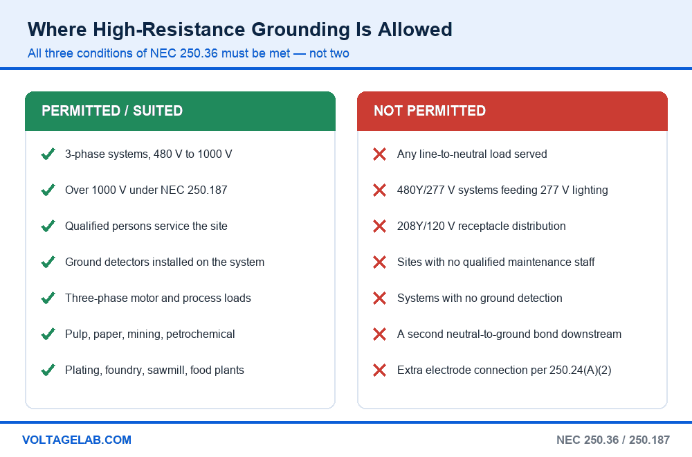
The Code treats impedance grounding as a permission with strings attached, not a default. NEC 250.20(D) sends you to one of two sections: 250.36 for 480 volts to 1000 volts, and 250.187 for systems over 1000 volts. The 2023 edition retitled 250.36 “Impedance Grounded Systems — 480 Volts to 1000 Volts,” but the substance is unchanged. Both open with the same three conditions, and all three must be met.
The three conditions, and where HRG is permitted
- Only qualified persons service the installation. An in-house electrical crew qualifies; a leased warehouse with a contractor’s phone number on the wall does not.
- Ground detectors are installed on the system. Not recommended — required. Without detection the first fault is invisible, which makes the design more dangerous than a solidly grounded one.
- Line-to-neutral loads are not served. Three-phase loads only — motors, heaters, rectifier and drive inputs.
- 3-phase systems in the 480 V to 1000 V band fall under 250.36; systems over 1000 volts fall under 250.187 with the same three conditions.
- Continuous-process industry is the natural home: pulp and paper, petrochemical, mining, plating, foundries, sawmills, food processing, and the mechanical side of large data centres — anywhere an unplanned trip costs more than the fault does.
Where high resistance grounding is not permitted or not sensible
- Any system serving line-to-neutral loads. 480Y/277 V with 277-volt lighting, or 208Y/120 V distribution. This disqualifies most commercial buildings outright.
- Anywhere a second solid ground reference exists. The exception in 250.24(A)(2) excludes impedance grounded systems from the additional outdoor grounding electrode connection, because a second solid reference would short the resistor out.
- Buildings without qualified maintenance staff. A fault nobody investigates is a system waiting for its second fault.
- Any system with a downstream neutral-to-ground bond. The neutral may only reach ground through the grounding impedance. One inadvertent bond defeats the whole design.
- Systems above roughly 5 kV. Charging current on medium-voltage cable systems is usually too large for a few amps to dominate, so low-resistance grounding is used instead.
The voltage rise you have to design for
When one phase faults to ground it sits near ground potential and the other two rise from line-to-neutral to full line-to-line voltage with respect to earth — on a 480-volt system, from 277 V to 480 V — and stay there as long as the fault is left on. Conductor insulation, surge arresters, surge capacitors and instrument transformers all have to be rated for continuous operation at that level. Check the arrester ratings before converting an existing solidly grounded system.
Choosing between HRG and the alternatives
Once the three conditions of 250.36 are satisfied, the decision comes down to what the facility cannot afford to lose.
| What the facility needs | High resistance grounding | Solidly grounded | Ungrounded |
|---|---|---|---|
| Process cannot trip on one ground fault | Yes | No | Yes |
| 277 V or 120 V loads on the same system | No | Yes | No |
| Fault can be traced without a shutdown | Yes — pulsing NGR | Not needed | Hard — no fault current |
| Simple overcurrent coordination | No — voltage-based detection | Yes | No |
| Works without qualified in-house staff | No — 250.36 condition | Yes | No |
None of this replaces the fundamentals. Start with the NEC Article 250 grounding and bonding overview, then read why the transformer neutral is earthed at all, and our guides to the grounding electrode and equipment grounding conductors. If the system is above 1000 volts, our breakdown of voltage class boundaries shows which side of the 250.36 / 250.187 line you are on.
Study smarter with VoltageLab
Built for electricians, apprentices, and electrical engineers who want faster practice and better exam prep.
⭐️ Join thousands of electricians upgrading their skills
Is high resistance grounding the right choice?
Pros
- A first ground fault does not shut the process down
- Phase-to-ground arc-flash energy drops to almost nothing
- No burned iron in motors and no blown holes in switchgear from ground faults
- Transient overvoltages are controlled, unlike a genuinely ungrounded system
- Pulsing NGR panels let a technician trace the fault to a feeder while it is live
- Faults get fixed on a planned outage instead of at 3 a.m.
Cons
- No line-to-neutral loads, so a second transformer is needed for lighting and receptacles
- Unfaulted phases sit at line-to-line voltage above ground until the fault is cleared
- A second ground fault on another phase becomes a phase-to-phase fault through the raceway
- Requires qualified staff who will actually chase the alarm
- Does nothing to reduce phase-to-phase or three-phase arc-flash energy
HRG buys uptime and ground-fault safety, and pays for it with a permanent maintenance obligation. A high-resistance grounded system whose alarm horn has been disabled is worse than a solidly grounded one, because the protection everybody assumes is there has been quietly removed.
Working with HRG systems in the field
Do
- Check the ground-detection panel before you start work — assume a fault is already on the system
- Treat the two unfaulted phases as being at line-to-line voltage to ground whenever the alarm is up
- Use the pulsing feature and a clamp-on ammeter to walk the fault down feeder by feeder
- Label the equipment so the next person knows the system is impedance grounded
- Verify the NGR itself during outages — measure it, do not just look at it
Avoid
- Bonding the neutral to a downstream enclosure — it shorts the resistor out completely
- Adding a 277 V control or lighting circuit “just this once”
- Silencing the alarm and leaving the fault for the next shift indefinitely
- Assuming your meter reading of 480 V to ground means something is wrong — on a faulted HRG system it is expected
- Adding long cable runs without rechecking the charging current against the resistor rating
The labelling point is not cosmetic. NEC 250.21(C) requires ungrounded systems to be marked at the source or first disconnect, and the same logic applies to a system that behaves nothing like the one an unfamiliar electrician expects. See our guide to electrical room signage requirements.
Frequently asked questions
What is high resistance grounding?
High resistance grounding is a system grounding method in which the neutral point of a three-phase source is connected to ground through a resistor rather than solidly. The resistor limits phase-to-ground fault current to roughly 5 to 10 amps, so a first ground fault alarms instead of tripping and the plant keeps running.
How much current flows in a high resistance grounded system during a ground fault?
Typically 5 to 10 amps, set by the resistor. On a 480-volt system a 55.4-ohm resistor gives about 5 amps, because 277 volts line-to-neutral divided by 55.4 ohms is 5. The value is chosen to exceed the system’s capacitive charging current while staying low enough to do no damage.
Which NEC section covers high resistance grounding?
NEC 250.36 for three-phase systems from 480 volts to 1000 volts, and NEC 250.187 for systems over 1000 volts. NEC 250.20(D) points you to whichever applies. In the 2023 edition, 250.36 was retitled “Impedance Grounded Systems — 480 Volts to 1000 Volts.”
Why can’t you serve 277-volt lighting from an HRG system?
Because NEC 250.36 and 250.187 both make “line-to-neutral loads are not served” a condition of using impedance grounding. The load current would have to return through the resistor, so the load would never see full voltage and the resistor would carry current continuously.
Is high resistance grounding the same as ungrounded?
No. Both keep running through a first ground fault, but an ungrounded system has no defined path to earth, so an intermittent arcing fault can charge the system capacitance and drive severe transient overvoltages. The resistor damps that mechanism, which is why HRG replaced ungrounded designs in industry.
Does high resistance grounding reduce arc flash?
For phase-to-ground faults, dramatically — there is only a few amps available, so there is almost no incident energy. It does nothing for phase-to-phase or three-phase arcing faults, so the arc-flash study and the PPE requirements do not go away. See our summary of the 2026 NFPA 70E arc flash updates.
What happens if a second ground fault occurs?
If it lands on a different phase, the two faults form a phase-to-phase short circuit through whatever metal connects them — conduit, enclosures, equipment grounding conductors. That is a full-magnitude fault in a path never designed to carry it, which is why the first fault has to be found promptly.
Can you convert an existing solidly grounded system to HRG?
Sometimes. You must remove every line-to-neutral load and every downstream neutral-to-ground bond, confirm insulation and surge arresters are rated for continuous line-to-line voltage to ground, calculate the charging current, and add ground detection. If the system feeds 277-volt lighting, the answer is no without a separate lighting transformer.
The bottom line
High resistance grounding earns its place wherever an unplanned trip costs more than the fault itself, and where people on site are competent to act on an alarm. It removes phase-to-ground arc-flash energy almost entirely, keeps equipment damage near zero, and turns a ground fault from an emergency into a work order — while still holding the system referenced to earth, the failing that made truly ungrounded systems obsolete.
The two restraints are the ones the Code writes down and the ones people forget: no line-to-neutral loads, ever, and a resistor whose let-through current stays above the system’s charging current as the plant grows. Get either wrong and the design either violates NEC 250.36 outright or quietly reverts to behaving like an ungrounded system. For the broader picture, see our overview of the purpose of grounding under Article 250.
FREE PRACTICE TOOL
Think you'd pass this on a real exam?
Test what you just read with instant-feedback quizzes built around real code questions — not generic trivia.
5
Code standards
10,000+
Active learners
100%
Free to start
Instant explanations on every answer, right or wrong
NEC, BS7671, AS/NZS, CEC, and DIN VDE covered
Bite-sized quizzes you can finish in 5 minutes
No signup required to try your first quiz
No account needed · Takes less than 2 minutes