

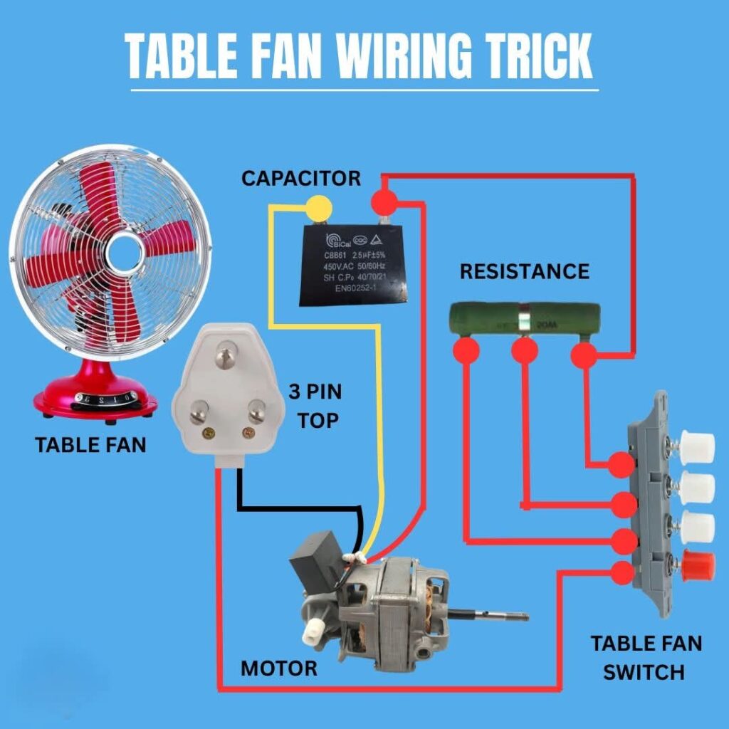
This diagram shows the complete wiring setup of a table fan, including the capacitor, resistance, motor, and switch. It helps you understand how each component works together to control the fan’s speed and ensure smooth operation.
Key Components:
- Capacitor: Provides the necessary phase shift for the fan motor to start.
- Resistance: Helps adjust the fan speed through different switch levels.
- Motor: Converts electrical energy into mechanical motion for the fan blades.
- 3-Pin Plug: Connects the fan safely to the power source.
- Fan Switch: Controls ON/OFF and speed levels.
Working Principle:
When the switch is turned ON, power flows through the resistance and capacitor to the motor, controlling speed based on the selected switch position. The 3-pin plug ensures proper grounding and safety during use.
Study smarter with VoltageLab
Built for electricians, apprentices, and electrical engineers who want faster practice and better exam prep.
⭐️ Join thousands of electricians upgrading their skills
⚡ Tip: Always check the capacitor rating (2.5µF–3µF) to match your fan model for optimal performance.
Practice more with electrical quizzes
NEC · BS7671 · AS/NZS · CEC · DIN VDE
