


An intersystem bonding termination (IBT) is a listed device or means, required by NEC 250.94, that provides an accessible external connection point for bonding communications systems — telephone, cable TV, satellite, and broadband — to a building’s electrical grounding electrode system. It must be external to the enclosure, have capacity for at least three bonding conductors, and be present at nearly every new service in the United States.
If you have ever roughed in a residential service and left a bare lug or small busbar on the outside of the meter can, you have installed an intersystem bonding termination — whether you knew the term for it or not. If you have never installed one at all, you may have been leaving completed services out of compliance with NEC 250.94 on every job.
Study smarter with VoltageLab
Built for electricians, apprentices, and electrical engineers who want faster practice and better exam prep.
⭐️ Join thousands of electricians upgrading their skills
The IBT is inspected, it is specifically defined in the NEC, and failing to provide it is a common residential and commercial inspection violation. This guide covers what an IBT is, why it exists, the exact NEC requirements that govern it, the six conditions a device must meet to qualify, the alternative “other means” method, which communications systems connect to it, and the 2023 NEC changes that affect where it can be installed.
Here’s what we cover:
- What an intersystem bonding termination is — and the hazard it prevents
- NEC 250.94 — scope, location, and when it is required
- The six conditions for a compliant IBT — NEC 250.94(A)(1) through (6)
- Why the IBT must be external to the enclosure
- The “other means” alternative — NEC 250.94(B) including the busbar option
- Which communications systems must bond to the IBT
- Multi-building applications — feeder-supplied structures
- The 2023 NEC change for IBT location — plus what inspectors look for
What Is an Intersystem Bonding Termination and Why Does It Exist?
An intersystem bonding termination is a listed device or means that provides a single, accessible connection point for bonding multiple systems to the building’s main electrical grounding electrode system. In plain terms: it is the place where the telephone company’s ground wire, the cable TV coax’s ground block bonding conductor, the satellite dish grounding wire, and broadband cable grounding conductors all connect to the building’s electrical ground.
The Hazard Being Prevented
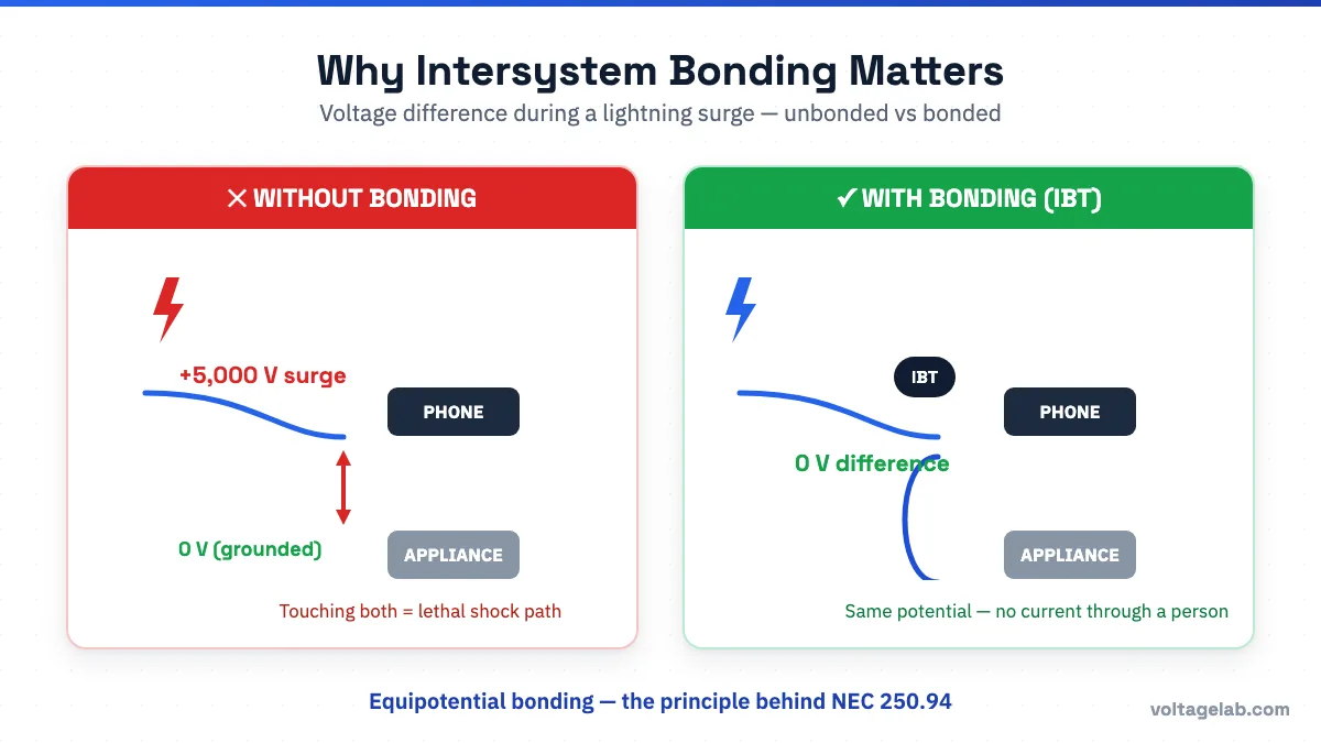
Without intersystem bonding, different systems entering a building can maintain different voltage potentials relative to earth. Under normal conditions the difference might be small and harmless. But during a lightning strike, a utility line surge, or a contact between a high-voltage line and a communication line, the voltage difference between an unbonded communications cable and a grounded electrical appliance can be lethal.
Consider a concrete scenario: lightning strikes near a utility pole and induces a voltage surge on the telephone line. That surge travels into the building on the telephone wire. If the telephone system is not bonded to the electrical grounding system, the surge voltage appears on the telephone line relative to the building’s grounded electrical system — including metal plumbing, outlet covers, and appliances. Anyone touching both a telephone and a grounded appliance simultaneously becomes the path for that voltage difference. Bonding the telephone system to the electrical grounding system eliminates the difference — both systems are at the same potential, so no dangerous current flows between them through a person or piece of equipment.
This is the concept of equipotential bonding — ensuring that all conductive systems and surfaces in a building are at the same electrical potential, so that no dangerous voltage differences exist between them. The IBT is the physical implementation point for that concept in the NEC.
Pass your electrical exam the first time
Practice real NEC exam questions with full code-referenced explanations and progress tracking — built for journeyman, master and apprentice exam prep.
Thousands of NEC practice questions with code-referenced answers
NEC 250.94 — Scope and Location Requirement
NEC 250.94 is titled “Bonding for Communications Systems.” It requires that communications system bonding conductor terminations be connected in accordance with one of two methods: the IBT device method (250.94(A)) or the “other means” method (250.94(B)).
Where an IBT (or Other Means) Is Required
Per NEC 250.94, an intersystem bonding termination must be provided at:
- The service equipment or metering equipment enclosure — for buildings served directly by the utility (the standard residential or commercial service)
- The disconnecting means for any building or structure supplied by a feeder or branch circuit — for a detached garage, outbuilding, barn, or any structure that receives power from another building rather than directly from the utility
The IBT must be located external to enclosures — on the outside of the service panel, meter can, or disconnect. This requirement is deliberate and has a specific reason, covered in the section below.
Exception — When an IBT Is Not Required
NEC 250.94 includes an Exception: means for connecting intersystem bonding conductors are not required where communications systems are not likely to be used in or on the building or structure.
In practice, this exception applies to industrial facilities, warehouses, or structures where there is no telephone line, cable TV, satellite dish, broadband, or other communications service being installed and none is likely to be installed in the future. For any standard residential or commercial building, the exception is essentially inapplicable — communications services are virtually always present or likely.
Why the IBT Must Be External to the Enclosure
The external location requirement exists for a licensing and access reason. Communications system installers — telephone technicians, cable TV installers, satellite dish installers, and network contractors — are licensed by their own trade licensing bodies and typically do not hold electrical contractor licenses. They are not permitted to open a service panel or disconnect to connect their bonding conductor.
If the bonding connection point were inside the electrical panel, communications installers could not legally access it. The result would be that telephone and cable TV systems simply would not be bonded — either because the installer could not open the panel, or because they opened it anyway in violation of their license and the NEC.
By requiring the IBT to be external to the enclosure, the NEC ensures that:
- Communications installers can complete the bonding connection without opening a panel
- Electricians set up the bonding point during the service installation
- Inspectors can verify the bonding point exists and is accessible without opening the service equipment
💡 Turn NEC 250.94 into practice questions.
The six IBT conditions are a favorite on journeyman and master exams. VoltageLab’s AI Quiz Generator creates unlimited exam-style questions on grounding and bonding — or any NEC article — so you can drill Article 250 until it sticks. Fresh questions every time.
The Six Conditions for a Compliant IBT — NEC 250.94(A)
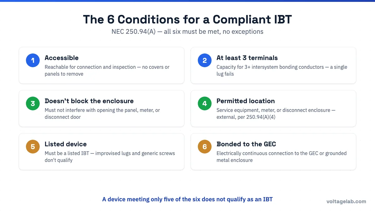
If the IBT device method is used (rather than the other means in 250.94(B)), the device must meet all six of the following conditions. This is the list that appears on journeyman and master exam questions about IBTs, and that inspectors verify on every service inspection.
Study smarter with VoltageLab
Built for electricians, apprentices, and electrical engineers who want faster practice and better exam prep.
⭐️ Join thousands of electricians upgrading their skills
| # | Condition | Plain-English Explanation |
|---|---|---|
| 1 | Accessible for connection and inspection | The IBT must be reachable without removing any building component, panel cover, or enclosure. It cannot be buried in a wall, installed inside a panel, or located where a ladder or tool is required for access under normal conditions. |
| 2 | Capacity for not less than three intersystem bonding conductors | The IBT must have at least three connection points (terminals or lugs) for the communications conductors — one for telephone, one for CATV, one for satellite or broadband, etc. A single-lug device does not qualify. |
| 3 | Not interfere with opening the enclosure | The IBT mounting and conductor arrangement must not block or obstruct the opening of the panel door, meter base door, or disconnect enclosure. A device that prevents the panel from being opened fails this condition. |
| 4 | At a permitted location | The IBT must be installed at one of the permitted locations: service equipment enclosure, meter enclosure, disconnecting means enclosure, or — per the 2023 NEC — “at the service equipment” (see the 2023 Change section below). |
| 5 | Be listed | The IBT device must be a listed device. Improvised bonding lugs, generic stainless screws, or unlisted ground bars do not satisfy the IBT listing requirement, even if they provide a physical bonding connection. |
| 6 | Bonded to the grounding electrode conductor (GEC) or to the metal enclosure | The IBT device must be electrically connected to the building’s grounding electrode system — either by direct connection to the GEC (using a listed connector) or by mounting on a metal enclosure that is itself bonded to the GEC. The bonding path must be electrically continuous. |
All six conditions must be met. A device that meets five of the six conditions does not qualify as an IBT. Inspectors looking for IBT compliance check all six, though conditions 1 (accessibility), 2 (three terminals minimum), and 3 (does not interfere with opening) are the ones most commonly failed in the field.
The “Other Means” Alternative — NEC 250.94(B)
NEC 250.94(B) permits an alternative to the listed IBT device. The “other means” option allows communications system bonding conductors to be connected to one of the following instead of an IBT device:
- Connections to grounded metal enclosures: A listed connection to the grounded metal enclosure of the service equipment, meter enclosure, or disconnect enclosure
- Connections to the GEC or grounding electrode system: A listed connection directly to the grounding electrode conductor or to the grounding electrode system — using a listed split-bolt connector, compression connector, or similar listed means
- Connections to an aluminum or copper busbar: A connection to a grounding busbar meeting the dimensional and installation requirements below
The Busbar Option — Dimensions and Requirements
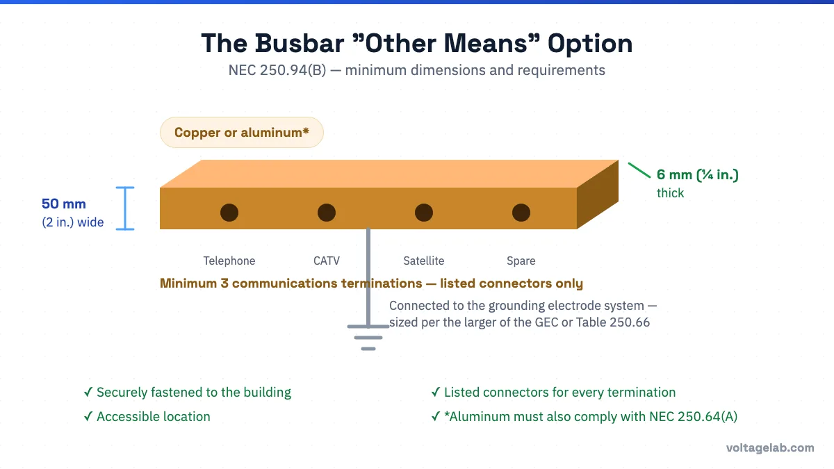
The busbar option under NEC 250.94(B) is a widely used alternative in residential construction. The busbar must meet all of the following:
- Material: aluminum or copper
- Minimum dimensions: not less than 6 mm thick × 50 mm wide (approximately 1/4 inch thick × 2 inches wide)
- Length: sufficient to accommodate at least three terminations for communications systems, plus additional connections
- Securely fastened to the building or structure, in an accessible location
- Connections made by listed connectors
- If aluminum busbars are used, the installation must also comply with NEC 250.64(A) (restrictions on use of aluminum conductors near masonry and certain environments)
- The busbar must be connected to the grounding electrode system by a conductor that is the larger of: (1) the largest GEC connected to the busbar, or (2) the conductor required by Table 250.66 based on the largest ungrounded service conductor
Many residential panel manufacturers include a compliant bonding lug or busbar on the exterior of the service panel that satisfies 250.94(B) as installed. In that case, the electrician does not need to install a separate IBT device — the panel’s listed exterior bonding provision satisfies the requirement.
| Feature | IBT Device — NEC 250.94(A) | Other Means — NEC 250.94(B) |
|---|---|---|
| Device must be listed? | Yes — IBT must be a listed device | Connections must use listed connectors or listed terminal means |
| Minimum terminals | 3 minimum (for 3 intersystem conductors) | Busbar must accommodate at least 3 communications connections |
| Location flexibility | Must be at one of the listed locations in 250.94(A)(4) | Connection to GEC, metal enclosure, or busbar — location tied to those elements |
| Common field application | Listed IBT device (ring terminal device or lug bar) mounted externally on meter can or panel | Exterior bonding lug built into the panel, or separate bonding busbar near service equipment |
Which Communications Systems Must Bond to the IBT
NEC 250.94 requires that bonding of communications systems be connected to the IBT or other means. The communications systems covered include all systems that bring conductors or cables into a building from outside the building’s electrical system:
| System Type | NEC Article | Notes |
|---|---|---|
| Telephone / telephone network interface device (NID) | Article 800 | The telephone company’s NID must be bonded; the bonding conductor from the NID connects to the IBT |
| Cable television (CATV) coaxial cable | Article 820 | The cable TV ground block at the building entry must be bonded; the bonding conductor from the ground block connects to the IBT |
| Satellite dish / antenna | Article 810 | Satellite dish and antenna ground blocks and lead-in conductors must be bonded; bonding conductor to the IBT |
| Network-powered broadband (fiber/FTTP) | Article 840 | The optical network terminal (ONT) ground must be bonded where it introduces metallic conductors into the building |
| Ethernet and network cabling (structured cabling) | Article 800 | Metallic components of the structured cabling system that are in contact with earth or exterior pathways must be bonded |
Practical note for residential work: On a typical single-family dwelling, the IBT or other means will typically serve the telephone NID, the CATV ground block, and the satellite dish bonding conductor. Each of these installers should be connecting their bonding conductor to the IBT — but they frequently do not, especially on existing buildings. The electrician’s responsibility is to provide the IBT and leave it accessible. The communications installers are responsible for making the connection when they install their systems.
Multi-Building Applications — Feeder-Supplied Structures
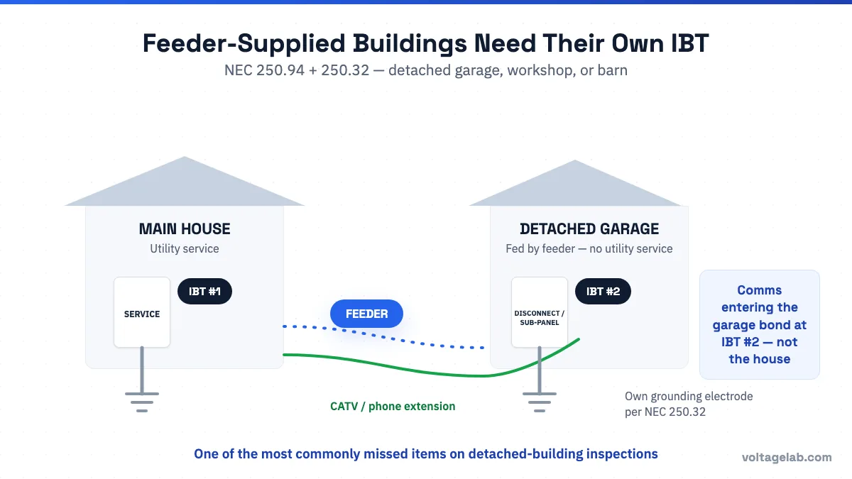
A detached garage, workshop, barn, or any separate structure that receives power from the main building (via a feeder rather than a separate utility service) also requires an IBT or other means at its disconnecting means. Per NEC 250.94, this means:
- The detached garage with its own sub-panel must have an IBT or compliant bonding means at the exterior of that sub-panel
- Any communications services (telephone, CATV, satellite, broadband) entering that separate structure must bond to the IBT at the structure’s disconnect — not at the main building’s IBT
- The GEC at the separate structure (required per NEC 250.32 for a separate structure with its own grounding electrode) is part of the grounding system that the IBT at that structure ties into
This multi-building requirement is frequently missed on inspections of detached garages and outbuildings, particularly when a communications cable (CATV or telephone extension) is run to the outbuilding.
The 2023 NEC Change — IBT Location Expansion
The 2020 NEC required the IBT to be installed at specific locations: the metal enclosure for the service equipment, meter socket enclosure, or disconnecting means enclosure, or connected to the metal enclosure housing the GEC with a 6 AWG copper conductor.
The 2023 NEC added an additional permitted location: the IBT may now also be installed “at the service equipment” — a phrase interpreted to allow the IBT to be mounted on the building wall directly adjacent to (but not necessarily on) the service equipment enclosure itself, as long as it is in close proximity and properly connected.
This addition acknowledged that some field situations make direct mounting to the service panel or meter enclosure difficult — particularly when the meter is on a utility pedestal, when the service entry conduit is the most accessible metallic element, or when the panel layout makes external device mounting impractical.
Note regarding the 2026 NEC: The 2026 NEC further clarified these provisions by permitting the IBT to be mounted directly to the building or structure itself, provided the connection is made with a minimum 6 AWG copper GEC. This recognizes that job site conditions do not always allow routing to a convenient metal enclosure. Verify which NEC edition your state has adopted before applying these newer provisions.
What Inspectors Look for on IBT Installations
When an electrical inspector reviews a service installation for IBT compliance, the following items are typically checked:
- Is an IBT or other means present? The most basic check. On many older installations and some new ones, the IBT is simply absent.
- Is it accessible? Is the IBT reachable without tools or building demolition? Is it in a location where communications installers can realistically connect their bonding conductors?
- Does it have at least three terminals? A single-lug device or a generic ground screw with only one connection point does not satisfy the three-terminal requirement.
- Does it interfere with the panel or meter door? A device mounted in the door swing path, or with bonding conductors that prevent the door from opening fully, fails condition 3.
- Is it listed? The inspector may check for a UL or other listing mark on the device.
- Is it bonded to the grounding electrode system? The IBT must be connected to the GEC or the grounded metal enclosure — not just mechanically attached to the outside of a panel without an electrical connection.
- Have communications systems actually connected their bonding conductors? On a final inspection where communications services are already installed, the inspector may check whether the telephone NID, CATV ground block, or satellite dish bonding conductors are connected to the IBT. Unconnected IBTs are noted, though the responsibility for making those connections belongs to the communications installers, not the electrician.
Common IBT Installation Mistakes
No IBT Installed at All
The most common violation. On many residential service installations, the IBT is either forgotten during rough-in or deemed unnecessary by installers who are not familiar with the requirement. NEC 250.94 applies to all new services and to existing services when alterations are made — it is not limited to new construction.
IBT Installed Inside the Panel
Placing the IBT inside the service panel satisfies the bonding requirement but violates the external location requirement of NEC 250.94. The IBT must be external so communications installers can access it without opening the panel.
Only One or Two Terminals — Insufficient Capacity
NEC 250.94(A)(2) requires the IBT to have capacity for not less than three intersystem bonding conductors. A single lug or two-lug device does not meet this requirement. Listed IBT devices are specifically designed with three or more terminals to satisfy this condition.
IBT Not Bonded to the Grounding System
An IBT physically attached to the outside of a panel but with no electrical connection to the panel’s metal enclosure or to the GEC is not compliant. The device must be bonded — either by direct metal-to-metal contact with the grounded enclosure or by a dedicated bonding conductor.
Missing IBT at Feeder-Supplied Outbuildings
Electricians who correctly install an IBT at the main house service frequently forget to install one at the disconnecting means of the detached garage or workshop supplied by a feeder. If any communications service is routed to that outbuilding, it needs a bonding connection point there too.
Conclusion
The intersystem bonding termination is a required component of every new service installation — a small device with a critical safety function. Without it, communications system conductors entering the building can maintain voltage differences from the electrical grounding system that create shock hazards and equipment damage risks during lightning and line surge events.
Four things to remember on every service installation:
- Install the IBT or other means at the service — external to the enclosure, accessible, with at least three terminals. This is a code requirement, not optional.
- All six conditions in NEC 250.94(A) must be met for a device to qualify as an IBT: accessible, three terminals minimum, does not interfere with panel opening, at a permitted location, listed, and bonded to the grounding system.
- Feeder-supplied buildings need their own IBT at their disconnecting means — not just the main building’s IBT.
- Your job is to provide the IBT. Connecting communications bonding conductors to it is the responsibility of the telephone, cable, and satellite installers — but they cannot do that job if you have not provided the device in an accessible location.
For related grounding and bonding topics, see our guides to Bonding Jumpers: Types, Sizing & NEC Code Rules and Grounding vs Bonding Bushings: NEC Differences Explained. And if you want to drill NEC 250 bonding rules until they’re second nature, check out the VoltageLab electrician app.
📱 Master grounding and bonding — and every other NEC topic.
VoltageLab gives you AI-generated practice tests, timed mock exams with NEC citations, flashcards, wiring guides, and a custom study plan built around your weak topics. Built for electricians and apprentices. Free on iOS and Android.
Frequently Asked Questions
What is an intersystem bonding termination?
An intersystem bonding termination (IBT) is a listed device or compliant means that provides an accessible external connection point for bonding communications systems — including telephone, cable TV, satellite, and broadband — to a building’s main electrical grounding electrode system. Required by NEC 250.94, the IBT ensures that all systems entering a building from outside maintain the same electrical potential as the building’s electrical grounding system, preventing dangerous voltage differences during lightning events and utility surges.
Where is the IBT required to be located?
Per NEC 250.94, the IBT must be located external to the enclosure at: (1) the service equipment or metering equipment enclosure, or (2) the disconnecting means for any building or structure supplied by a feeder or branch circuit. The external location is required so that communications system installers (telephone, CATV, satellite technicians) can connect their bonding conductors without needing to open a licensed electrical panel.
What are the six conditions for a compliant IBT under NEC 250.94(A)?
The IBT must be: (1) accessible for connection and inspection, (2) consist of terminals with capacity for at least three intersystem bonding conductors, (3) not interfere with opening the service or metering enclosure, (4) installed at a permitted location per 250.94(A)(4), (5) listed, and (6) bonded to the grounding electrode conductor or to the metal enclosure on which it is installed. All six conditions must be satisfied; a device meeting only five does not qualify.
What is the “other means” option under NEC 250.94(B)?
NEC 250.94(B) allows communications bonding conductors to be connected by other means instead of a listed IBT device. Permitted other means include: a listed connection to the grounded metal enclosure of the service or disconnect, a listed connection directly to the GEC or grounding electrode, or a connection to an aluminum or copper busbar that is at least 1/4 inch thick × 2 inches wide, securely fastened, accessible, and connected to the grounding electrode system by a conductor sized per the larger of the requirements in 250.94(B)(3). Many residential panels include a compliant exterior bonding provision that satisfies 250.94(B).
Do I need an IBT at my detached garage if it is fed by a feeder from the main house?
Yes. NEC 250.94 requires an IBT or other means at the disconnecting means for any building or structure supplied by a feeder or branch circuit — not only at the utility service. If your detached garage has a sub-panel fed by a feeder from the main house, you must provide an IBT or compliant bonding means at the exterior of the garage’s disconnecting means. If any communications service (telephone, CATV, satellite, broadband) runs to the garage, its bonding conductor must connect to the IBT at the garage, not at the main house IBT.
FREE PRACTICE TOOL
Think you'd pass this on a real exam?
Test what you just read with instant-feedback quizzes built around real code questions — not generic trivia.
5
Code standards
10,000+
Active learners
100%
Free to start
Instant explanations on every answer, right or wrong
NEC, BS7671, AS/NZS, CEC, and DIN VDE covered
Bite-sized quizzes you can finish in 5 minutes
No signup required to try your first quiz
No account needed · Takes less than 2 minutes