


When electricians search “high voltage cable,” they are almost always looking for what the NEC and the electrical industry technically classify as medium voltage (MV) cable. Understanding the distinction matters — because it determines which NEC articles govern the installation, which cable types are required, what insulation level to specify, and who is qualified to make the terminations.
Quick answer: What electricians call “high voltage cable” in the field is almost always Type MV (medium voltage) cable — governed by NEC Article 315 for the 2,001V–35,000V AC range. True “high voltage” under ANSI/IEEE standards doesn’t start until 69 kV, which is utility transmission territory outside typical NEC scope.
Study smarter with VoltageLab
Built for electricians, apprentices, and electrical engineers who want faster practice and better exam prep.
⭐️ Join thousands of electricians upgrading their skills
This guide covers everything an electrician needs to know about medium voltage cable under the 2023 NEC: the voltage classifications, Type MV cable types and construction, the three insulation levels and when each applies, shielding requirements, the 2023 NEC reorganization that created new dedicated articles for these installations, and the qualified persons requirement that directly affects who can legally make MV terminations.
- The voltage classification system — where “high voltage” actually starts
- The 2023 NEC reorganization: new Articles 235, 245, 305, 315, and 495
- Type MV cable: MV-90 vs. MV-105, construction layers, and insulation types
- The three insulation levels — 100%, 133%, and 173% — and what determines which to use
- Shielding requirements and the new 2023 NEC shielding sections
- Minimum conductor size, ampacity tables, and the January 2026 listing requirement
- Qualified persons requirement for MV joints and terminations
- Where MV cable is used in the field
Voltage Classification — Where “High Voltage” Actually Starts
The term “high voltage” is used loosely in the field and means different things in different contexts. For NEC work, the relevant threshold is 1,000 volts AC (1,500 volts DC) — above this level, a different set of NEC articles applies. For cable specification, ANSI and IEEE define voltage classifications more precisely.
| Classification | Voltage Range | Governing NEC Articles (2023) | Who Encounters It |
|---|---|---|---|
| Low Voltage (LV) | Up to 1,000V AC / 1,500V DC | NEC Chapters 1–4 (Articles 100–490) | Most residential, commercial, and light industrial electricians daily |
| Medium Voltage (MV) | 1,001V–69 kV (ANSI/IEEE); NEC Article 315 covers 2,001V–35,000V AC | NEC Articles 235, 245, 305, 315, 495 (new in 2023 NEC) | Industrial electricians, utility contractors, substation crews, wind/solar installers |
| High Voltage (HV) | 69 kV–230 kV (ANSI/IEEE) | Primarily utility standards (NESC, ANSI), not typical NEC scope | Transmission utility crews — outside typical electrical contractor scope |
| Extra-High Voltage (EHV) | Above 230 kV | Utility transmission — outside NEC scope | Bulk power transmission utility crews |
Table 1: Voltage Classifications — NEC vs. ANSI/IEEE Definitions
The practical takeaway: What most electricians call “high voltage cable” — the cable feeding industrial switchgear, unit substations, wind turbine step-up transformers, and utility distribution equipment on construction sites — is medium voltage cable under ANSI/IEEE standards. The NEC covers it in Article 315 for the 2,001V–35,000V AC range. The term “high voltage cable” in a search context almost always refers to this MV range, not transmission-level HV cable.
The 2023 NEC Reorganization — New Articles for Over-1,000V Systems
The 2023 NEC made significant structural changes to how medium voltage installations are organized. Previous editions had requirements scattered across various articles or grouped in Article 311. The 2023 NEC created dedicated articles for each aspect of over-1,000V systems, making it substantially easier to find the applicable rules.
| NEC Article (2023) | Previous Location | What It Covers |
|---|---|---|
| Article 235 | Scattered in Articles 210, 215, 230 | General requirements for branch circuits, feeders, and services over 1,000V AC / 1,500V DC |
| Article 245 | Article 240 (partial) | Overcurrent protection for systems over 1,000V AC / 1,500V DC |
| Article 305 | Former Article 399 | General wiring methods and materials for systems over 1,000V AC / 1,500V DC |
| Article 315 | Former Article 311 (2020 NEC) | Type MV medium voltage conductors, cable, cable joints, and cable terminations — 2,001V to 35,000V AC; 2,001V to 2,500V DC |
| Article 495 | Article 490 (partial) | Equipment rated over 1,000V AC / 1,500V DC |
Table 2: New 2023 NEC Articles for Systems Over 1,000V AC / 1,500V DC
Pass your electrical exam the first time
Practice real NEC exam questions with full code-referenced explanations and progress tracking — built for journeyman, master and apprentice exam prep.
Thousands of NEC practice questions with code-referenced answers
If you are working from a 2020 NEC, the medium voltage cable requirements were in Article 311. In the 2023 NEC, that content was expanded and relocated to Article 315. Verify which edition your state has adopted before applying code requirements.
💡 Lost track of which article moved where?
The 2023 reorganization scattered MV content across five new articles — easy to cite the wrong one from memory. Watch a short video lesson on NEC Article 315 and its companion articles (235, 245, 305, 495) with VoltageLab’s Watch and Quiz feature, then quiz yourself immediately with AI-generated questions to lock it in.
NEC Article 315 — Type MV Cable: Scope and Application
NEC 315.1 defines the scope: Article 315 covers the use, installation, construction specifications, and ampacities for Type MV medium voltage conductors, cable, cable joints, and cable terminations for systems rated from 2,001 volts to 35,000 volts AC and 2,001 volts to 2,500 volts DC.
Type MV cable is the listing designation — the “MV” suffix tells you this cable has been listed and manufactured for medium voltage service. It is not a generic term for any cable that happens to operate above 1,000V. Using unlisted cable or inappropriately rated cable in MV applications is a code violation and a serious safety hazard.
MV-90 vs. MV-105 — The Two Temperature Ratings
Two Type MV cable designations are defined by their maximum conductor operating temperature:
| Designation | Max. Conductor Temperature | Typical Application | Relative Cost |
|---|---|---|---|
| Type MV-90 | 90°C (194°F) | Most standard MV feeder and service entrance applications; the default choice for most installations | Lower |
| Type MV-105 | 105°C (221°F) | High-capacity feeders, locations with elevated ambient temperature, applications where short-circuit withstand capability is critical, or where higher sustained ampacity is needed | Higher |
Table 3: Type MV Cable Temperature Ratings — NEC Article 315 (2023 Edition)
The number in the designation (90 or 105) directly indicates the maximum continuous operating temperature. MV-105 carries more current than MV-90 for the same conductor size because its insulation can tolerate higher temperatures. When specifying MV cable for a feeder that experiences frequent overloads or high ambient conditions, MV-105 provides more thermal margin.
Type MV Cable Construction — Layer by Layer
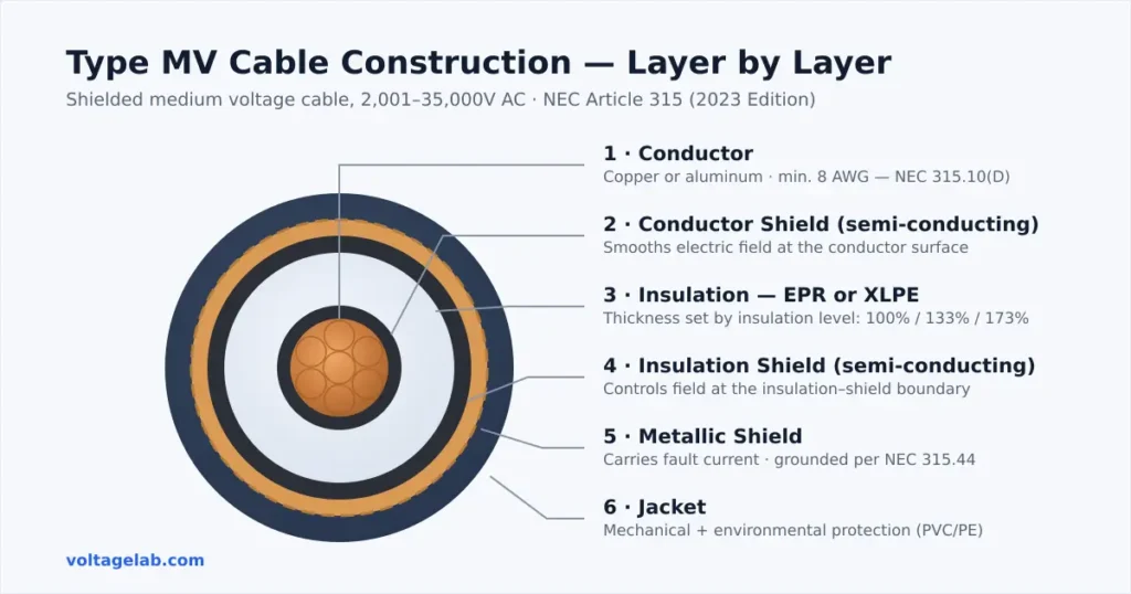
Understanding what is inside an MV cable explains why it performs differently from low-voltage cable — and why terminations require specialized training. A shielded Type MV cable has six distinct layers, each with a specific function:
| Layer | Material | Purpose |
|---|---|---|
| 1. Conductor | Copper or aluminum (stranded or solid) | Carries the current. Minimum size 8 AWG per NEC 315.10(D). |
| 2. Conductor Shield (semi-conducting layer) | Semi-conducting thermoplastic or thermosetting material | Provides a smooth, uniform surface at the conductor-insulation interface to eliminate electrical stress concentrations caused by conductor stranding. Without this, high electric field gradients at strand edges would cause insulation damage. |
| 3. Insulation | EPR (ethylene propylene rubber) or XLPE (cross-linked polyethylene) | Primary voltage insulation — prevents current flow to any adjacent conductive surface. Thickness depends on voltage rating and insulation level (100%, 133%, or 173%). |
| 4. Insulation Shield (semi-conducting layer) | Semi-conducting thermoplastic or thermosetting material | Provides a smooth, uniform interface at the insulation-to-shield boundary. Controls the electric field distribution and prevents surface discharge on the outside of the insulation. |
| 5. Metallic Shield | Copper tape, copper concentric wires, or lead sheath | Returns fault current, provides EMI shielding, and confines the electric field within the cable. Must be grounded at one or both ends per NEC 315.44. |
| 6. Jacket | PVC, PE, or other listed thermoplastic/thermosetting material | Mechanical protection and environmental sealing. For direct-burial applications, must be rated for direct burial. For sunlight-exposed installations, must be sunlight-resistant. |
Table 4: Type MV Shielded Cable Construction — Layers Inside Out
Insulation Materials — EPR vs. XLPE
NEC 315.10(A) requires MV cable insulation to be thermoplastic or thermosetting. Two materials dominate the industry:
- EPR (Ethylene Propylene Rubber): Thermoset insulation with excellent flexibility, good heat resistance, and strong resistance to moisture and chemicals. Preferred for industrial applications where the cable must be pulled through conduit, handled in cold conditions, or exposed to chemical environments. Higher dielectric losses than XLPE but superior flexibility.
- XLPE (Cross-Linked Polyethylene): Thermoset insulation that is slightly less expensive than EPR, has lower dielectric losses (slightly more efficient for transmission), but is stiffer and more prone to moisture treeing over time in wet environments. Common in utility distribution and substation applications where flexibility is less critical.
Insulation Levels — 100%, 133%, and 173%
This is one of the most important — and most misunderstood — aspects of MV cable selection. The insulation level does not refer to a percentage of the cable’s voltage rating. It refers to the thickness of the insulation relative to what is needed for the cable’s operating voltage, and which level applies depends on how quickly a ground fault can be cleared by the system’s protection scheme.
The logic: When a single-phase-to-ground fault occurs in an ungrounded or high-impedance grounded system, the unfaulted phases can be stressed at line-to-line voltage (rather than line-to-neutral voltage) for the duration of the fault. The longer the fault can persist, the more insulation thickness is needed to withstand that elevated stress without failure.
Study smarter with VoltageLab
Built for electricians, apprentices, and electrical engineers who want faster practice and better exam prep.
⭐️ Join thousands of electricians upgrading their skills
| Insulation Level | Ground Fault Clearing Time | Typical System Grounding | When to Specify |
|---|---|---|---|
| 100% | Within 1 minute (relay protection clears the fault rapidly) | Solidly grounded, low-resistance grounded, or low-impedance grounded systems | Most utility distribution and industrial systems with fast protective relay tripping. The insulation is sized for normal phase-to-neutral voltage stress. |
| 133% | Within 1 hour (system can operate with fault present temporarily) | High-impedance grounded or ungrounded systems with fault detection/annunciation | Systems designed to continue operating briefly while a fault is located and cleared in an orderly manner — common in industrial process plants where immediate shutdown is not acceptable. |
| 173% | Indefinite (no reliable time limit for fault clearing) | Ungrounded systems in industrial facilities where orderly shutdown is required and qualified personnel maintain the system | Industrial facilities where: qualified personnel maintain and supervise the system, the 133% requirement cannot be met, the facility requires orderly shutdown for personnel/equipment protection, and the fault can be cleared during a controlled shutdown. This is a restrictive option — not for general use. |
Table 5: MV Cable Insulation Levels — When Each Is Required (NEC Article 315 and ICEA/AEIC Standards)
Plain-English summary: Use 100% for well-protected, fast-clearing systems. Use 133% when you need the cable to survive a ground fault for up to an hour while the system keeps running. Use 173% only in controlled industrial environments with qualified oversight and no reliable fast-clearing scheme.
Note: Insulation levels apply only to shielded MV cables. Non-shielded cables (where permitted) are over-insulated by design and do not follow this percentage convention.
Shielding Requirements — NEC 315.10(C), 315.44, and 315.45
Shielding is required for most Type MV cable installations. Without the metallic shield, the electric field around the cable is uncontrolled and can cause corona discharge and surface tracking on the insulation — both of which progressively damage the insulation and eventually cause failure.
When Shielding Is Required (NEC 315.10(C))
Shielding is required for MV cables in general. Two narrow exceptions permit non-shielded conductors in specific circumstances:
- Exception 1 — Up to 2,400V: Non-shielded, listed conductors may be used up to 2,400V if: the insulation is resistant to electric discharge and surface tracking (or covered with a material that is), wet-location installations have an overall nonmetallic jacket or continuous metallic sheath, and insulation/jacket thicknesses comply with NEC Table 315.10(B).
- Exception 2 — Up to 5,000V, existing industrial installations only: Non-shielded conductors may replace existing non-shielded conductors in industrial establishments only, when qualified personnel install and service the system, the same insulation/tracking-resistant requirements are met, and the conditions of Exception 1 for wet locations are satisfied.
Outside these narrow exceptions: shield your MV cable.
New 2023 NEC Shielding Sections
NEC 315.44 — Shielding at Type MV Cable Installations: Added in the 2023 NEC, this section addresses shielding requirements for MV cable installations — ensuring the metallic shield is properly grounded and maintained to control the electric field and safely carry fault current. For the general grounding principles this section builds on, see our NEC Article 250 grounding overview.
NEC 315.45 — Shielding at Type MV Cable Joints and Terminations: Also new in 2023, this section requires that MV cable joints and terminations be provided with means to connect the metallic insulation shield to ground where required. An unterminated or improperly grounded shield at a termination point concentrates electric stress at the shield cutback and can cause rapid insulation failure at that point — a serious hazard.
Listing Requirements — Including the January 2026 Deadline
NEC 315.6 requires that Type MV cables be listed. The 2023 NEC expanded this requirement:
New in 2023 (effective January 1, 2026): MV cable joints, MV cable terminations, and connectors must also be listed. Previously, only the cables themselves required listing — the joints and terminations did not. The effective date of January 1, 2026 was set to give the industry time to exhaust existing inventory of unlisted joints, terminations, and connectors.
Practical impact: As of January 1, 2026, any new MV installation must use listed cable, listed cable joints, listed terminations, and listed connectors. Unlisted MV accessories — even from reputable manufacturers — are no longer code-compliant for new installations after that date.
Qualified Persons Requirement — NEC 315.30
NEC 315.30 requires that persons who make up MV joints and terminations have documented training and experience in the installation of MV cable accessories. This is a safety requirement driven by the specific hazards of MV terminations:
- Improperly prepared terminations concentrate electric field stress at the shield cutback, causing rapid insulation breakdown
- MV terminations require precise preparation steps (stress relief cones, controlled shield removal, correct heat-shrink or cold-shrink sequence) that must be executed correctly
- A failed MV termination can result in an arc flash event at medium voltage — significantly more energetic and dangerous than a low-voltage arc flash
“Documented training” typically means manufacturer-provided training on the specific termination system being used, or recognized apprenticeship/employer training programs that include MV termination procedures. An electrician who is fully qualified for low-voltage work is not automatically qualified to perform MV terminations without this additional documented training.
Ampacity — Type MV Cable Ratings
NEC Article 315 contains ampacity tables specific to MV cable. The tables are organized by voltage range (2,001–5,000V and 5,001–35,000V) and temperature rating (MV-90 and MV-105).
Representative ampacity values from the NEC Article 315 tables (copper conductors, single conductors in conduit, 90°C ambient correction factors not applied — verify against actual NEC tables):
| Conductor Size | MV-90 Ampacity | MV-105 Ampacity |
|---|---|---|
| 8 AWG | 85A | 90A |
| 6 AWG | 110A | 115A |
| 4 AWG | 140A | 150A |
| 2 AWG | 180A | 195A |
| 1/0 AWG | 230A | 250A |
| 2/0 AWG | 265A | 285A |
| 4/0 AWG | 340A | 365A |
| 350 kcmil | 445A | 480A |
| 500 kcmil | 540A | 580A |
| 750 kcmil | 665A | 720A |
| 1,000 kcmil | 780A | 840A |
Table 6: Representative Type MV Cable Ampacity Values — NEC Article 315 (2023 Edition, Copper, 2,001–5,000V)
Always verify from the actual NEC 2023 Article 315 tables before sizing MV conductors. Correction factors for ambient temperature, burial depth, and installation method apply and can significantly affect the final conductor size selection.
Installation Methods for Type MV Cable
NEC Articles 305 and 315 together govern installation of MV cable. Permitted installation methods include:
- In conduit/raceway: The most common installation method. Conduit must be rated for the voltage and must be continuous and properly supported. PVC conduit is commonly used for MV underground runs; rigid metal conduit for above-grade or in-building runs where physical protection is critical.
- Direct burial: Permitted for Type MV cable with a jacket listed for direct burial. Three-conductor Type MV cables are typically approved for direct burial by the manufacturer. Single-conductor cables generally require conduit for direct-buried applications.
- Cable tray: Must be approved for cable tray use and sunlight-resistant where exposed to sunlight (NEC 392). This must be specified when ordering the cable — not all MV cable is rated for cable tray.
- Messenger-supported wiring: Above-grade outdoor installations where the cable is supported by a messenger wire.
Bending Radius
MV cables have significantly larger minimum bending radii than low-voltage cable due to the thickness of the insulation system. Exceeding the bending radius compresses the insulation, potentially causing micro-voids that become points of insulation failure under voltage. Always follow the manufacturer’s published minimum bending radius — typically expressed as a multiple of the cable’s overall diameter (e.g., 12× OD for shielded MV cable). Verify the manufacturer’s requirements for each specific cable.
Where MV Cable Is Used in the Field
Electricians encounter Type MV cable most frequently in these applications:
- Industrial feeders: Distribution from utility service entrance transformers (typically 4 kV–15 kV) to plant substations or unit substations within a facility. Often 15 kV class cable (rated for 5 kV–15 kV systems).
- Utility distribution connections: Primary distribution cables from utility padmount or network transformers to commercial and industrial service points. These installations may be utility-installed but inspected under local AHJ authority in many jurisdictions.
- Substation-to-substation feeders: Interconnecting distribution substations within large industrial complexes, universities, airports, or military bases.
- Renewable energy: MV cable is standard on wind and solar farm collection systems. Wind turbine step-up transformers (typically 690V/34.5 kV) use 35 kV class MV cable on the primary side. Solar collection circuits aggregate multiple inverters into 34.5 kV feeders.
- Data centers and campuses: Large facilities with on-site distribution substations use MV feeders to distribute power across the campus before stepping down at load centers.
Conclusion
Type MV cable — what most electricians refer to as “high voltage cable” — is governed in the 2023 NEC primarily by Article 315, with supporting requirements in Articles 235, 245, and 305. The key decisions in every MV cable installation are:
- Temperature rating: MV-90 for most applications; MV-105 where higher ampacity or thermal margin is needed.
- Insulation level: 100% for fast-clearing systems; 133% for systems that may run faulted up to one hour; 173% only for specific supervised industrial applications.
- Shielding: Required for all MV cable except within the narrow 2,400V and 5,000V exceptions for existing industrial installations.
- Listing: Cable, joints, terminations, and connectors must all be listed — with the joint/termination/connector requirement effective January 1, 2026 under the 2023 NEC.
- Qualified persons: MV joints and terminations must be made by personnel with documented training and experience in MV cable accessories — per NEC 315.30.
For the broader landscape of cable types and standards beyond MV, see our Electrical Cable Types & Standards guide.
FAQ
What is considered “high voltage” cable under the NEC?
The NEC uses the threshold of 1,000 volts AC (1,500 volts DC) to separate standard wiring methods from those for “over 1,000 volt” systems. Cable for medium voltage systems — typically 2,001V to 35,000V AC — is covered in NEC Article 315 as Type MV cable. By ANSI/IEEE standards, true “high voltage” begins at 69 kV and is primarily utility transmission territory. What most electricians and contractors refer to as “high voltage cable” in field and commercial contexts is technically medium voltage (MV) cable under the NEC and industry standards.
What is the difference between Type MV-90 and MV-105 cable?
MV-90 and MV-105 refer to the maximum continuous conductor operating temperature. Type MV-90 cable is rated for 90°C maximum; Type MV-105 is rated for 105°C maximum. MV-105 has a higher current-carrying capacity (ampacity) than MV-90 for the same conductor size because its insulation tolerates higher operating temperatures. MV-105 is typically used where higher sustained ampacity is needed, in elevated ambient temperature environments, or where better short-circuit withstand capability is required. MV-90 is the standard choice for most typical MV feeder applications.
What do the 100%, 133%, and 173% insulation levels mean for MV cable?
These levels refer to insulation thickness relative to the minimum needed for the cable’s rated voltage, and the appropriate level depends on how quickly the system’s protection can clear a ground fault. 100% level cable is used on systems where ground faults are cleared within one minute by relay protection — typical for solidly grounded systems. 133% level is used where the system may operate with a ground fault for up to one hour. 173% level is for controlled industrial environments with no reliable time limit for fault clearing, where qualified personnel supervise the system and orderly shutdown is possible. These levels apply only to shielded cables.
Who is qualified to make medium voltage cable terminations?
NEC 315.30 requires that persons making MV cable joints and terminations have documented training and experience in the installation of MV cable accessories. An electrician qualified for low-voltage work is not automatically qualified for MV terminations. The typical path to qualification is manufacturer-provided training on the specific termination system (heat-shrink, cold-shrink, or premolded systems), plus supervised field experience. This requirement exists because improperly prepared MV terminations can fail rapidly and catastrophically — potentially causing an arc flash event at medium voltage.
What changed in the 2023 NEC regarding medium voltage cable?
The 2023 NEC reorganized medium voltage requirements into new dedicated articles: Article 235 (branch circuits, feeders, services over 1,000V), Article 245 (overcurrent protection over 1,000V), Article 305 (wiring methods over 1,000V), Article 315 (Type MV cable, replacing former Article 311), and Article 495 (equipment over 1,000V). Article 315 expanded previous Article 311 content to include requirements for MV cable joints and terminations. New Section 315.6 required listing of MV cable joints, terminations, and connectors — effective January 1, 2026. New Sections 315.44 and 315.45 added shielding requirements for MV cable installations and at termination points. New Section 315.30 codified the qualified persons requirement for MV joint and termination work.
FREE PRACTICE TOOL
Think you'd pass this on a real exam?
Test what you just read with instant-feedback quizzes built around real code questions — not generic trivia.
5
Code standards
10,000+
Active learners
100%
Free to start
Instant explanations on every answer, right or wrong
NEC, BS7671, AS/NZS, CEC, and DIN VDE covered
Bite-sized quizzes you can finish in 5 minutes
No signup required to try your first quiz
No account needed · Takes less than 2 minutes