

Location Symbols for Installations
 | Machine, general symbol * function etc |
 | Load, general symbol * details |
 | Motor starter, general symbol * Indicates type etc. |
 | Socket-outlet, general symbol |
| | Twin Socket-outlet, general symbol |
 | Switched socket-outlet |
| | Twin Switched socket-outlet |
 | Switch, general symbol |
 | 2 way switch, single pole |
 | Intermediate switch |
 | Pull switch, single-pole |
 | Push button |
 | Clock, general symbol |
 | Bell (Audible) |
 | Buzzer (Audible) |
 | Siren (Audible) |
| Horn | |
 | Telephone handset, general symbol |
Popular Symbols
Making and breaking current
| Switch | |
| Switch- fuse | |
 | Fuse-switch |
Isolating
| Isolator (Disconnector), general symbol | |
 | Disconnector – fuse (fuse combination unit) |
 | Fuse – disconnector |
Making, breaking and isolating
 | Switch – disconnector |
 | Switch – disconnector – fuse (fuse combination unit) |
 | Fuse – switch – disconnector |
 | Capacitor, general symbol |
 | Inductor, coil, winding or choke |
 | Inductor, coil, winding or choke with magnetic core |
 | Semi Conductor Diode – general symbol |
 | Microphone |
 | Loudspeaker |
| Antenna, general symbol | |
 | Machine, general symbol * Function M=Motor G=Generator |
| Generator, general symbol | |
 | Indicating instrument, general symbol * function V = Voltmeter A = Ammeter etc. |
| Integrating instrument or Energy meter * function Wh = Watt-hour VArh = Volt ampere reactive hour | |
 | Lamp, or signal lamp, general symbol |
Lamps & Lighting
The following table provides the commonly used electrical wiring schematic symbols for push-buttons and lamps which comply with the IEC and BS Electrical Symbols. We have included the Normally Open and Normally Closed status for each contact.
 | Lamp (Standard) |
 | Lamp Standard |
 | Filament Lamp |
 | Lamp (Flashing) |
 | Lighting outlet position – general symbol |
 | Fluorescent luminaire |
| Wall mounted luminaire | |
 | Self – contained emergency lighting luminaire |
| Emergency lighting luminaire (or special circuit) |
 | Light Emitting Diode (LED) |
Connectors and Earthing
The following table provides the commonly used electrical wiring schematic symbols for connectors which comply with the IEC and BS Electrical Symbols. These connectors include plug and socket, coaxial, terminal and earth connectors.
Study smarter with VoltageLab
Built for electricians, apprentices, and electrical engineers who want faster practice and better exam prep.
⭐️ Join thousands of electricians upgrading their skills
| Plug Male | Socket (plug female) | ||
| Coax Plug Male | Slow Operating Relay – Delay On | ||
| Wire Connections (Two Wires) |  | Wire Connections (crossed) | |
 | Wires Crossing (Not Connected) | Terminal Connector | |
 | Terminal Block |  | Earth Connection |
 | Noiseless Earth |  | Protective Earth |
 | Chassis Earth |  | Equipotentiality |
General Symbols
| Ammeter | Voltmeter | ||
 | Circuit Breaker |  | Selector Switch (N/O) Normally Open (N/C) Normally Closed |
 | Contactor (N/C) |  | Contactor (N/O) |
 | Limit Switch |  | Thermal Overcurrent |
 | Mechanical Interlock | Voltage Transformer | |
 | Potentiometer |  | Solenoid Valve |
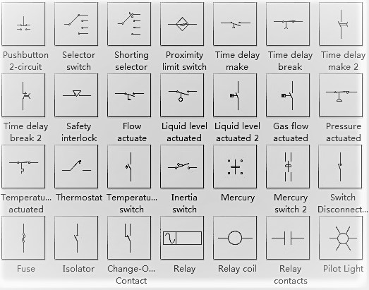
Contacts and Switches
The following table provides the IEC and BS Electrical Symbols for contacts. We have included the Normally Open and Normally Closed status for each contact
| Normally open Contact (N/O) | Normally Closed Contact (N/C) | ||
| Change Over or 2 way Contact Made position | Fused Switch Open Contact (N/O) | ||
| Limit Switch (N/O) | Limit Switch (N/C) | ||
 | Flow Switch (N/O) |  | Flow Switch (N/C) |
 | Time Delay (N/O) Delay on Closing | Time Delay (N/O) Delay on re-opening | |
| Thermal Switch – Overload (N/O) |  | Thermal Switch – Overload (N/C) | |
| Temperature Switch (N/O) | Temperature Switch (N/C) | ||
| Pressure Switch (N/O) |  | Pressure Switch (N/C) |
Push-buttons
The following table provides the commonly used electrical wiring schematic symbols for push-buttons and lamps which comply with the IEC and BS Electrical Symbols. We have included the Normally Open and Normally Closed status for each contact.
| Normally Open PB (N/O) | |
 | Normally Closed PB (N/C) |
| Emergency Stop PB (N/O) Indication Contact | |
 | Emergency Stop PB (N/C) |
 | Pull Switch (N/O) |
| Pull Switch (N/C) | |
| Turn/Rotary Switch (N/O) | |
 | Turn/Rotary Switch (N/C) |
Coils and Relays
| Electrical Symbols – Coils and Relays | |
| The following table provides the commonly used electrical wiring schematic symbols for coils and relays which comply with the IEC and BS Electrical Symbols | |
 | Contractor Coil |
 | Relay with AC Supply |
 | Slow Release Relay Delay Off |
| General Relay (DC Supply) | |
 | Slow Operating Relay Delay On |
 | Mechanically Latched Relay |
Semi Conductors
The following table provides the commonly used electrical wiring schematic symbols for coils and relays which comply with the IEC and BS Electrical Symbols
| Contractor Coil |
| Relay with AC Supply |
| Slow Release Relay Delay Off |
| General Relay (DC Supply) | |
| Slow Operating Relay Delay On |
| Mechanically Latched Relay |
Other Symbols
 | Three-phase winding – Star |
 | Changer, general symbol Converter, general symbolNotes: (1) If the direction of change is not obvious, it may be indicated by an arrowhead on the outline of the symbol. (2) A symbol or legend indicating the input or output quantity, waveform etc. may be inserted in each half of the general symbol to show the nature of change. |
 | Rectifier |
 | Inverter |
 | Primary cell – longer line positive, shorter line negative |
 | Battery |
| Fuse link, rated current in amperes |
Practice more with electrical quizzes
NEC · BS7671 · AS/NZS · CEC · DIN VDE
