


NEC Chapter 9 Table 8 is the conductor properties table used for circular mil area, bare conductor diameter, stranding data, and DC resistance at 75°C. Electricians use it for voltage drop calculations, bonding jumper sizing, conductor identification, and exam problems that require conductor resistance or circular mil values.
This guide explains how to read NEC Chapter 9 Table 8, which columns matter in the field, how circular mils work, when to use Table 8 instead of Table 5 or Table 9, and which mistakes cause wrong calculations.
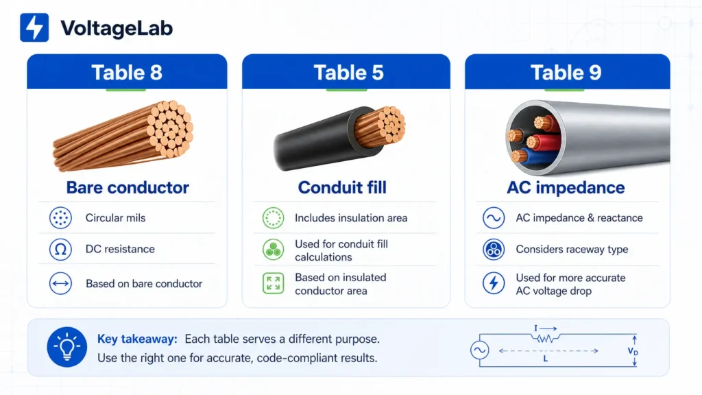
- Use Table 8 for bare conductor properties, circular mils, and DC resistance.
- Use Table 5 or Table 5A for conduit fill because those tables include insulation area.
- Use Table 9 for more precise AC voltage drop where impedance and raceway type matter.
Quick Answer: What Is NEC Chapter 9 Table 8 Used For?
NEC Chapter 9 Table 8 is used when a calculation needs the metal conductor’s area, diameter, stranding, or resistance. The most common uses are voltage drop calculations, conductor size identification, and bonding jumper sizing where circular mil area controls the answer.
Study smarter with VoltageLab
Built for electricians, apprentices, and electrical engineers who want faster practice and better exam prep.
⭐️ Join thousands of electricians upgrading their skills
| Task | Table 8 data used | Field or exam use |
|---|---|---|
| Voltage drop calculation | Circular mil area or DC resistance | Branch circuit and feeder voltage drop checks |
| Bonding jumper sizing | Circular mil area | 12.5% rule for large parallel service conductors |
| Conductor identification | Diameter and circular mil area | Matching an unlabeled bare conductor to an AWG or kcmil size |
| Resistance correction | Ohms per 1,000 ft at 75°C | Adjusting resistance when conductor temperature differs from 75°C |
| Conduit fill | Do not use Table 8 | Use NEC Chapter 9 Table 5, Table 5A, and Table 4 instead |
For faster field checks, pair this guide with VoltageLab’s Voltage Drop Calculator, Conduit Fill Calculator, and Wire Size Calculator.
Where Does Table 8 Fit in NEC Chapter 9?
NEC Chapter 9 is the table section of the Code, and Table 8 is the table for conductor properties. Chapter 9 does not tell you how to install wiring by itself. It gives you reference data used by calculation rules found elsewhere in the NEC.
| NEC Chapter 9 table | Primary use | Do not confuse it with |
|---|---|---|
| Table 1 | Maximum conduit and tubing fill percentages | Conductor resistance or circular mil area |
| Table 4 | Raceway dimensions and internal area | Bare conductor diameter |
| Table 5 | Insulated conductor area for conduit fill | Bare conductor circular mil area |
| Table 5A | Compact aluminum building wire dimensions | Standard Class B stranded conductor dimensions |
| Table 8 | Bare conductor area, diameter, stranding, and DC resistance | Insulated conductor area for conduit fill |
| Table 9 | AC resistance and reactance for 600-volt cables | Simple DC resistance values from Table 8 |
The fastest way to remember the difference is this: Table 8 is about the metal conductor; Table 5 is about the insulated conductor; Table 9 is about AC impedance.
💡 Watch it explained, then prove you know it.
VoltageLab’s Watch and Quiz feature gives you short NEC-focused lessons, then tests you with practice questions so Table 8, Table 5, and Table 9 do not blend together on exam day.
Pass your electrical exam the first time
Practice real NEC exam questions with full code-referenced explanations and progress tracking — built for journeyman, master and apprentice exam prep.
Thousands of NEC practice questions with code-referenced answers
What Is a Circular Mil?
A circular mil is the area of a circle with a diameter of 1 mil, where 1 mil equals 0.001 inch. NEC Table 8 uses circular mils because round conductor area becomes easy to calculate: the circular mil area equals the conductor diameter in mils squared.
Area in circular mils (CM) = diameter in mils x diameter in milsFor example, a solid conductor with a diameter of 0.1019 inch has a diameter of 101.9 mils. Square 101.9 and you get about 10,384 circular mils, which matches the NEC Table 8 value for 10 AWG solid copper: about 10,380 CM.
Circular Mil Calculation Steps
- Measure the conductor diameter in inches.
- Multiply inches by 1,000 to convert inches to mils.
- Square the diameter in mils.
- Compare the result with NEC Chapter 9 Table 8.
Large conductors are normally shown in kcmil. One kcmil equals 1,000 circular mils, so 250 kcmil equals 250,000 circular mils.
How Do You Read NEC Chapter 9 Table 8?
You read NEC Chapter 9 Table 8 by starting with the conductor size, then moving across the row to find area, stranding, diameter, and DC resistance. Most field and exam calculations use the circular mil column or the ohms-per-1,000-ft resistance column.
Size: AWG and kcmil
The size column identifies conductors by AWG or kcmil. Table 8 includes small AWG conductors and large kcmil conductors, so it can support both small calculation questions and large feeder or service calculations.
Area: mm² and Circular Mils
The area columns show the bare conductor’s metal area. In NEC-based voltage drop calculations, the circular mil value is the main number you need for the K-factor method.
Single-phase voltage drop = (2 x K x I x L) / CM
Three-phase voltage drop = (1.732 x K x I x L) / CM
For a full voltage drop walkthrough, see VoltageLab’s guide to voltage drop calculation questions on NEC electrical exams.
Stranding
The stranding columns show strand quantity and strand diameter. You usually do not need those values for a basic exam problem, but they matter when identifying conductor construction, checking a project specification, or matching conductors with listed terminations.
Overall Diameter and Area of Bare Conductor
The diameter columns describe the bare conductor, not the insulated wire. This distinction matters. The number is useful for conductor identification and some termination work, but it is not the number you use for conduit fill.
DC Resistance at 75°C
The resistance columns give DC resistance at 75°C in ohms per kilometer and ohms per 1,000 feet. Table 8 separates uncoated copper, coated copper, and aluminum because each conductor material has a different resistance.
Key NEC Chapter 9 Table 8 Values to Know
You do not need to memorize all of NEC Table 8, but knowing common circular mil and resistance values saves time on exams and field estimates. The values below are representative Table 8 values for uncoated copper conductors at 75°C and should be verified against the official NEC table before final design or publication.
| Conductor size | Circular mils | DC resistance, ohms/kFT | Why electricians use it |
|---|---|---|---|
| 14 AWG | 4,110 | 3.14 | Small branch circuit voltage drop checks |
| 12 AWG | 6,530 | 1.98 | Standard 20A branch circuit reference |
| 10 AWG | 10,380 | 1.24 | 30A circuits and upsized long runs |
| 8 AWG | 16,510 | 0.778 | Larger branch circuits and smaller feeders |
| 6 AWG | 26,240 | 0.491 | EVSE, dryers, and feeder calculations |
| 4 AWG | 41,740 | 0.308 | Common feeder calculations |
| 2 AWG | 66,360 | 0.194 | Large feeder and service work |
| 1/0 AWG | 105,600 | 0.122 | Service and large feeder sizing |
| 2/0 AWG | 133,100 | 0.0967 | Service conductor calculations |
| 3/0 AWG | 167,800 | 0.0766 | Large service conductors |
| 4/0 AWG | 211,600 | 0.0608 | Bonding jumper and large feeder calculations |
| 250 kcmil | 250,000 | 0.0515 | Large feeder work where Table 9 may also matter |
| 350 kcmil | 350,000 | 0.0367 | Commercial service and feeder work |
| 500 kcmil | 500,000 | 0.0258 | Large commercial feeders and parallel sets |
Aluminum has higher resistance than copper for the same AWG size. For exact aluminum values, use the aluminum resistance column in NEC Chapter 9 Table 8, not a rough multiplier.
Study smarter with VoltageLab
Built for electricians, apprentices, and electrical engineers who want faster practice and better exam prep.
⭐️ Join thousands of electricians upgrading their skills
What Do the NEC Table 8 Notes Mean?
The notes under NEC Chapter 9 Table 8 tell you when the listed resistance and diameter values can be used directly and when they need adjustment. These notes matter because conductor coating, temperature, material, and stranding style can change the final calculation.
Note 1: Resistance Values Match Only the Listed Conditions
Table 8 resistance values apply to the listed conductor material, coating, stranding, and 75°C temperature. If any of those conditions change, the listed resistance may not apply directly.
Note 2: Temperature Changes Resistance
Table 8 gives resistance at 75°C. When a calculation requires a different conductor temperature, use the Table 8 temperature correction formula.
R2 = R1 x [1 + alpha(T2 - 75)]| Variable | Meaning | How to use it |
|---|---|---|
| R1 | Resistance at 75°C | Look up in NEC Table 8 |
| R2 | Resistance at new temperature | Final corrected result |
| alpha | Temperature coefficient | Use the value given in Table 8 Note 2 for the conductor material |
| T2 | New conductor temperature in °C | Use the operating temperature required by the calculation |
Note 3: Compact and Compressed Stranding Change Diameter
Compact and compressed stranding reduce conductor diameter compared with standard Class B stranding. That affects physical fit and conduit-fill-related choices, but it does not change the circular mil area for a conductor of the same size.
Note 4: IACS Conductivity Explains Copper vs Aluminum
IACS means International Annealed Copper Standard. Table 8 uses copper and aluminum conductivity assumptions, which is why aluminum has higher resistance than copper at the same conductor area.
How Is Table 8 Used for Voltage Drop?
For the common K-factor voltage drop method, NEC Table 8 supplies the circular mil area used in the denominator of the formula. Larger circular mil area means lower resistance and lower voltage drop for the same load current and run length.
Voltage Drop Example Using Table 8
Example: A 120V, single-phase circuit uses 12 AWG copper conductors, carries 16A, and has a one-way length of 75 ft. Estimate voltage drop using the K-factor method.
- Find circular mil area for 12 AWG copper in Table 8: 6,530 CM.
- Use copper K value: 12.9.
- Use the single-phase formula:
VD = (2 x K x I x L) / CM. - Calculate:
VD = (2 x 12.9 x 16 x 75) / 6,530. - Result: about 4.74 volts.
- Percentage voltage drop:
4.74 / 120 x 100 = 3.95%.
For exam prep, remember that NEC voltage drop language is commonly addressed through informational notes, not a general mandatory branch-circuit voltage drop rule. Always read the exact question wording and the cited NEC section.
Code note: This article uses NEC 2023 as the reference baseline. Before publishing or using these values for design, verify the final conductor values against the official NEC edition adopted in your jurisdiction.
💡 Get step-by-step help with electrical calculations.
VoltageLab’s AI Study Coach walks you through voltage drop, wire sizing, and NEC calculation problems with explanations, not just answers. It is built for apprentices, journeyman candidates, and working electricians who need the math to make sense.
How Is Table 8 Used for Bonding Jumper Sizing?
Table 8 is used for bonding jumper sizing when the NEC rule is based on total circular mil area. For large parallel service conductors, you add the circular mil area per phase, apply the percentage rule, then choose the next standard conductor size from Table 8.
Example: A service has four parallel 400 kcmil copper conductors per phase. The total area per phase is:
4 x 400,000 CM = 1,600,000 CMIf the required bonding jumper area is 12.5% of that total:
1,600,000 CM x 0.125 = 200,000 CMThe next common Table 8 conductor size at or above 200,000 CM is 4/0 AWG at 211,600 CM. A 3/0 AWG conductor at 167,800 CM would be too small for that example.
Table 8 vs Table 5 vs Table 9: Which One Should You Use?
Use Table 8 for bare conductor properties, Table 5 or 5A for conduit fill, and Table 9 for AC impedance calculations. Choosing the wrong table is one of the fastest ways to get a wrong exam answer or a bad field calculation.
| Question you are answering | Correct table | Reason |
|---|---|---|
| What is the circular mil area of this conductor? | Table 8 | Table 8 lists bare conductor area. |
| What is the DC resistance of this copper or aluminum conductor? | Table 8 | Table 8 lists DC resistance at 75°C. |
| How much conduit space does this insulated conductor occupy? | Table 5 or Table 5A | Conduit fill requires insulated conductor area, not bare metal area. |
| What is the precise AC voltage drop for a large conductor in a specific raceway? | Table 9 | Table 9 includes AC resistance and reactance by raceway type. |
For raceway sizing, start with VoltageLab’s NEC conduit fill calculator or the guide to proper sizing of conduits and raceways.
Common NEC Chapter 9 Table 8 Mistakes
The most common Table 8 mistakes come from using the right-looking number for the wrong calculation. Table 8 is powerful, but it only works when the problem actually asks for bare conductor properties or DC resistance.
Using Table 8 for Conduit Fill
Do not use Table 8 circular mil values for conduit fill. Conduit fill depends on the full insulated conductor area from Table 5 or Table 5A and the raceway area from Table 4.
Using DC Resistance for Every AC Calculation
Table 8 gives DC resistance. That is acceptable for many field and exam voltage drop calculations, especially smaller branch circuits and feeders. For precise AC work on large conductors or inductive loads, Table 9 is usually the better reference.
Picking the Coated Copper Column by Mistake
Standard building wire is usually uncoated copper under insulation, not tinned copper. Use the coated copper column only when the installed conductor is actually coated or tinned.
Forgetting the 75°C Baseline
Table 8 resistance values are based on 75°C conductor temperature. If a problem gives a different conductor temperature and asks for precision, apply the Table 8 temperature correction formula.
Practice Questions: NEC Chapter 9 Table 8
Practice questions help lock in which NEC Chapter 9 table belongs to which calculation. These questions are written in the same style you might see in NEC exam prep, but always verify final answers against the official Code book and your exam’s adopted NEC edition.
Question 1
A calculation asks for the circular mil area of a 12 AWG copper conductor. Which NEC Chapter 9 table should you use?
Answer: NEC Chapter 9 Table 8. Table 8 lists bare conductor circular mil area. Table 5 is for insulated conductor area used in conduit fill.
Question 2
You are calculating conduit fill for three 6 AWG THHN conductors. Should you use Table 8 circular mil values?
Answer: No. Conduit fill uses insulated conductor area from NEC Chapter 9 Table 5 or 5A, not bare conductor circular mil values from Table 8.
Question 3
A precise AC voltage drop calculation for a large feeder asks you to account for raceway type and reactance. Which table is the better starting point?
Answer: NEC Chapter 9 Table 9, because Table 9 includes AC resistance and reactance values for 600-volt cables by raceway type.
FAQ: NEC Chapter 9 Table 8
What is NEC Chapter 9 Table 8 used for?
NEC Chapter 9 Table 8 is used for conductor properties: circular mil area, bare conductor diameter, stranding data, and DC resistance at 75°C. Electricians most often use it for voltage drop calculations, conductor identification, and bonding jumper sizing where circular mil area is part of the NEC calculation.
Is Table 8 used for conduit fill?
No. Table 8 is not the correct table for conduit fill because it only describes the bare metal conductor. Conduit fill requires the area of the complete insulated conductor from NEC Chapter 9 Table 5 or Table 5A, plus the raceway area from Table 4 and fill percentages from Table 1.
What is the difference between Table 8 and Table 9?
Table 8 gives DC resistance and bare conductor properties. Table 9 gives AC resistance and reactance values for 600-volt cables and separates values by raceway type. Use Table 8 for common K-factor voltage drop and circular mil calculations. Use Table 9 when the problem requires AC impedance, reactance, or raceway-specific data.
Why does Table 8 use 75°C resistance values?
Table 8 uses 75°C as a standard reference temperature for resistance values. Since conductor resistance changes with temperature, Table 8 Note 2 provides a correction formula for calculations at other temperatures. For many field and exam problems, the 75°C value is used directly unless the problem asks for temperature correction.
What does kcmil mean in Table 8?
kcmil means thousand circular mils. One kcmil equals 1,000 circular mils, so a 250 kcmil conductor has an area of 250,000 circular mils. The kcmil system keeps large conductor sizes readable and connects directly to Table 8 circular mil calculations.
Conclusion
NEC Chapter 9 Table 8 is the table you use when a calculation depends on the conductor metal itself. It gives circular mil area, bare conductor dimensions, stranding details, and DC resistance at 75°C. It is essential for voltage drop, conductor identification, and bonding jumper calculations.
Keep three rules straight: use Table 8 for bare conductor properties, use Table 5 or 5A for conduit fill, and use Table 9 when precise AC impedance matters. If you are studying for an exam, practice identifying which table the question is really asking for before you start the math.
Next, review voltage drop calculation questions, Ohm’s Law, and the VoltageLab Electrician App for NEC study tools, video lessons, practice questions, and jobsite calculation help.
FREE PRACTICE TOOL
Think you'd pass this on a real exam?
Test what you just read with instant-feedback quizzes built around real code questions — not generic trivia.
5
Code standards
10,000+
Active learners
100%
Free to start
Instant explanations on every answer, right or wrong
NEC, BS7671, AS/NZS, CEC, and DIN VDE covered
Bite-sized quizzes you can finish in 5 minutes
No signup required to try your first quiz
No account needed · Takes less than 2 minutes